diy solar

diy solar

Help with battery bank bus bars

onahill

New Member
Joined
Dec 4, 2022
Messages
15
Greetings,

I joined a couple of months ago and have been lurking and learning a lot ever since. This is a great forum. I have been off grid since I built my house over 25 yrs ago. I recently upgraded my system after deciding to make the plunge for LifePo4 batteries. I went from 12 volt to 24 volts, and I replaced my beast of a Trace inverter with the compact Victron Multiplus 24 3000/70. And I am finally done with lead acid batteries, having purchased 4 Ampheretime 12v 300 amp/hr LifePo4 batteries. I run Linux, not Windows, so it was very difficult configuring the Multiplus for LifePo4 batteries, but I finally got it with a lot of help from this forum and Oracle VirtualBox.

When I put my original system together, nobody was talking about using bus bars for the battery bank. Now it seems it's the only sure way to give batteries a chance to balance, so I'm going to try them. I’m pretty sure this setup will work, but I wanted some assurance and feedback.
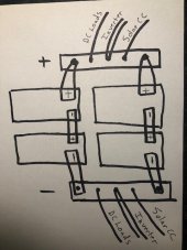
battery-sketch.jpg
Sorry for the crude sketch. The 4 batteries are configured 2s/2p for 600amphrs at 24 volts. I am going to use a 1/8 x 1 copper bar to tie the 2 batteries in series. The larger bus bars are 1/8 x 3”. On the ends of the bar I plan to have the leads to put the batteries in parallel. In the center I was planning to hook up the inverter. And between those 2, my leads for the Victron charge controller and my DC loads. I also have a Victron Smart Shunt. The only cable that will be used is for the parallel connections. I want to make them as short as possible, but that is the logical place for the smart shunt, right?. Is there a better place? What about my monitoring leads? Can I just put those with the parallel terminals, or should I create some smaller terminals in the bus bar for those?

The large bus bars are 24” long. I was thinking that I could get away with 18” for them, and use the remaining 6” for a stronger series connection bus bar. Do you think that is necessary? Or is the 1” wide enough?

Any comments or observations would be greatly appreciated.
 
Is the Ampere time series supported? You need some T type fuses in there somewhere.

As for ampacity of bar. https://www.copper.org/applications/electrical/busbar/busbar_ampacities.html
Thank you for your reply.
Yes, their manual shows my exact configuration, just with cables connecting them in series/ parallel, then a lead going to the bus bars. To me it makes more sense to use the bus bar to join the batteries in parallel as well. I guess my main question is will my setup work? Using the bus bar to put the batteries in parallel as well as a place to connect inverter, charge controller, and dc loads. And having the battery on both ends with the inverter in the middle?
I have a Trace 250 amp DC disconnect/breaker in between the battery and the inverter.
 
Why not use 24 volt batteries and avoid the problem of voltage drift within the series?
 
Why not use 24 volt batteries and avoid the problem of voltage drift within the string?
Because I didn't know I was moving to 24 volt when I bought them. And, well, I already bought the 12v.
 
Don't see why it wouldn't work, make sure batteries are secured so there is no stress on terminals.
Another option would be to parallel 2 12v packs then series so you only have one connection going to the buss bar. I think that makes sense? An even cruder drawing I made on my phone ?.

Edit, would that even work?
 

Attachments

  • Screenshot_20230129-093214.jpg
    Screenshot_20230129-093214.jpg
    130 KB · Views: 15
I also have a Victron Smart Shunt. The only cable that will be used is for the parallel connections. I want to make them as short as possible, but that is the logical place for the smart shunt, right?. Is there a better place?
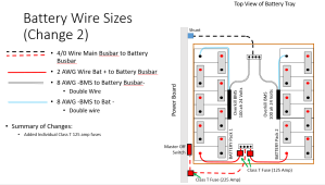
The shunt should be the first thing on the negative side after the batteries are combined, This is the way I wired mine.
1675002656175.png
What about my monitoring leads? Can I just put those with the parallel terminals, or should I create some smaller terminals in the bus bar for those?
Out of the two possible monitoring leads, mine is hooked to the battery on a terminal. You can tap into a busbar if you want a more professional installation.

I did not connect terminal 2.
When I put my original system together, nobody was talking about using bus bars for the battery bank. Now it seems it's the only sure way to give batteries a chance to balance, so I'm going to try them.
I don’t believe the batteries should be connected with busbars unless the battery terminals are receptive to them. For example with the lead terminals on most car batteries and golf cart batteries, busbars don’t for on. Also, when you have 1” copper bar, it needs to fit just right, there is no play in it, not even 1/64 th on an inch. IF the batteries can be connected with busbar easy, this is a NON-ISSUE.

As in my diagram, I used 2 AWG with 100 amps max from the bank to connect the batteries to the busbar. I actually see no more than 40 amps from each bank.

I’m not sure if your busbar to inverter is a single wire or one, in practice I’ve found putting two studs on a busbar post impossible with bigger inverter wire.

Because I didn't know I was moving to 24 volt when I bought them. And, well, I already bought the 12v.
I don’t think the batteries in series will be an issue. You can always monitor cell health via a BMS app, and if that doesn’t work, you can use a voltmeter and if they are out of balance charge them. There’s millions of systems out there with batteries in series. I have also found that the 24 volt batteries that is twice is big is twice as heavy, and that plays a factor in installations, especially in a tight to install place.
 
I thought that was the point of bus bars? A bus bar connecting them in series. Won't that help?
Each logical 24 volt battery is made from 2 physical 12 volt batteries.
The busbars don't do anything to address voltage drift of the physical 12 volts batteries within the 24 volt logical batteries.
 
Ideally you should have gotten 24V Battery Packs for a 24V system instead of kludging it with 12V batteries.
Honestly, you'll be better off selling the 12V ones and replacing that with 24V Packs in Parallel.
Lack of planning & thinking things through first always costs more money - call it a lesson learned.
 
I want to say again I don’t think voltage drift is an issue.

At worst, there is some preventative maintenance where the batteries are charged individually to be whole. It is 8 cells and whether thode 8 cells are in one case or two won’t make a huge difference. Millions of systems have smaller voltage batteries in series to make a bigger battery. Plenty of reputable battery suppliers like Trojan sell the single cell large capacity batteries, like 3.2 volt 400+ amp hours because if you need a battery that big, its a bit heavy.
 
The shunt should be the first thing on the negative side after the batteries are combined, This is the way I wired mine.
View attachment 132016

Out of the two possible monitoring leads, mine is hooked to the battery on a terminal. You can tap into a busbar if you want a more professional installation.

I did not connect terminal 2.

I don’t believe the batteries should be connected with busbars unless the battery terminals are receptive to them. For example with the lead terminals on most car batteries and golf cart batteries, busbars don’t for on. Also, when you have 1” copper bar, it needs to fit just right, there is no play in it, not even 1/64 th on an inch. IF the batteries can be connected with busbar easy, this is a NON-ISSUE.

As in my diagram, I used 2 AWG with 100 amps max from the bank to connect the batteries to the busbar. I actually see no more than 40 amps from each bank.

I’m not sure if your busbar to inverter is a single wire or one, in practice I’ve found putting two studs on a busbar post impossible with bigger inverter wire.


I don’t think the batteries in series will be an issue. You can always monitor cell health via a BMS app, and if that doesn’t work, you can use a voltmeter and if they are out of balance charge them. There’s millions of systems out there with batteries in series. I have also found that the 24 volt batteries that is twice is big is twice as heavy, and that plays a factor in installations, especially in a tight to install place.
Thank you for taking the time. I will put SmartShunt between neg battery terminal and bus bar. My monitoring leads I'm not sure, but now I know I have options. I have 4/0 cable from bus bar to inverter, leftover from my 12 volt system. The batteries will be connected to the bus bar with 2/0. I am using a 1" bus bar to connect them in series, so I will make sure the fit very snug. I am using a bus bar here because I thought it would help balance the 2 batteries. If I'm not really gaining anything, it's not worth it. And I agree, while batteries in series are not perfect, it is very common practice.
 
I agree, while batteries in series are not perfect, it is very common practice.
That is LEAD Acid thinking and it stops there. Yes people kludge 12V to 24 or 48 using LFP Batteries but it is not correct for LFP or any other Lithium Based chemistry. Remember that each battery has it's own BMS and will do it's own Independent thing as is should to protect itself regardless of other packs in the setup. WHEN a Battery in a series string cuts off the other take the full hit be it charge / discharge and most BMS' will NOT handle this well - there are numerous posts on this even though most people will not fess up when they screw up (publicly) some do so that the others will learn from their mistakes.

Remember that Lead Acid has zero smarts, no BMS' and are essentially "Brute Force" tech while anything lithium is Millivolt & Milliohm sensitive & reactive due to the tech involved.
Okay. I take your point. Thank you.
 
Don't see why it wouldn't work, make sure batteries are secured so there is no stress on terminals.
Another option would be to parallel 2 12v packs then series so you only have one connection going to the buss bar. I think that makes sense? An even cruder drawing I made on my phone ?.

Edit, would that even work?
Thanks. I wanted to keep cable connections to a minimum.
 
I'm sorry to be the messenger but a lot of folks just won't. I am not trying to be mean or anything but don't want to see you go down that rabbit hole when it can be avoided. Ultimately it is YOUR Pocket Book, Risk, Liability and the consequences over the long term, so it is entirely up to you. I've been here since the start of this forum and into solar etc (100% offgrid ++) for longer and it is a sad & terrible thing when someone burns up their battery packs for no good reason. BTW: I was a Heavy Lead (Rolls Surette battery bank) for years before joining the Bright Side of LFP.

Aside from selling the existing 12V packs, you can go a bit drastic, tear them apart and change them to 24V by combining the cells from 2 12V batteries so you have an 8S String with an 8S BMS. * THIS DEPENDS on if the Busbars are Welded or Bolted to the cells within the packs, AmperTime has used both methods in building their batteries.

The Victron will pull up to 125A to @ 24V and deliver 3000W + extra for surge handling up to 6000W or 250A draw.
 
  • Like
Reactions: mib
Thank you for your reply.
Yes, their manual shows my exact configuration, just with cables connecting them in series/ parallel, then a lead going to the bus bars. To me it makes more sense to use the bus bar to join the batteries in parallel as well. I guess my main question is will my setup work? Using the bus bar to put the batteries in parallel as well as a place to connect inverter, charge controller, and dc loads. And having the battery on both ends with the inverter in the middle?
I have a Trace 250 amp DC disconnect/breaker in between the battery and the inverter.
The Trace 250 is fine between the inverter and bank, but you need a Class T on each series pair. In between the + terminal and the busbar. This would prevent one pair in series from discharging at high current into the other if a fault occurs in the other series pair. Note @chrisski has the Class T's in the proper location.

Anytime you put LFP into parallel strings each string requires a Class T.
 
Ideally you should have gotten 24V Battery Packs for a 24V system instead of kludging it with 12V batteries.
Honestly, you'll be better off selling the 12V ones and replacing that with 24V Packs in Parallel.
Lack of planning & thinking things through first always costs more money - call it a lesson learned.
What is the issue with doing something like 2S2P with LFP batteries? I was at cross roads on my noodling as to whether to go 12v or 24 and had already started with 12v batteries. I saw in a couple of different places where it was recommended to not go series with LFP, and not knowing why, decided to stay with 12v in parallel.
 
Back
Top