diy solar

diy solar

Help with hybrid AGM/LIFEPO4 setup

Werdna

New Member
Joined
Dec 19, 2021
Messages
15
I am after some inputs from the pro's on a proposed hybrid AGM/LIFEPO4 setup for my 4x4.
All the loads i want to run for camping are already wired off the main 105ah factory AGM battery and I don't want to rewire everything for them to run off the aux battery.
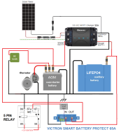
The idea is to keep everything running off the AGM and use the Li to top up the AGM as power is consumed. Basically the Li is acting as a charger for the AGM.
The Li bank will be 4 x 10⁵ah prismatics and a 100a JBD or Daly BMS.
Alternator is 190a, water cooled.

With the engine running, the Renogy 50a DC-DC charger will charge the Li with the correct parameters and will even lock out charging at low temps (we never see below freezing here anyway), while the alternator charges the AGM. The 5 pin relay is supplying no power to engage the Victron battery protect so the Li is charging only - no load.
With the engine off, DC-DC will disconnect itself and the 5 pin relay will engage the battery protect. At this point the Li should start trickle charging the AGM at around 13.6v until it runs out of juice, at 12.0v the battery protect will cut out to protect the cells. I guess at some point in the voltage curve there isn't enough volts to trickle charge anymore and it will start drawing power from both batteries. When the batter protect disconnects the lithium at 12.0v, i guess the AGM is at 50% SOC and needs charging too. But will still easily have enough juice to start the car.
While the engine is off, the Renogy should take input from the solar and charge the Li first, then the AGM if the Li is full.

Any suggestions? I can always change the battery protect for a small Victron DC-DC converter or charger but both increase the cost and I am not sure if they offer any real benefit.
porsche dual battery.png
 

Attachments

  • porsche dual battery.png
    porsche dual battery.png
    293.4 KB · Views: 5
It would make a more simple and reliable systen to move the DC load feed to the lithium battery. Just use the conventional system of a starter and service battery. Moving one single cable from one battery to another is easily implemented.

Mike
 
Unfortunately it's not that simple. "Dc loads" refers to the whole vehicle electrical system. To separate the camping loads from the regular vehicle loads would be a fair bit of work. There's 6 x 12v outlets, plus the stereo, then some lighting. This car has a fairly complicated electrical system and i want to leave as much of the factory wiring alone as possible.
 
To separate the camping loads from the regular vehicle loads would be a fair bit of work.
Imho that’s work you need to do
use the Li to top up the AGM as power is consumed. Basically the Li is acting as a charger for the AGM.
The Li bank will be 4 x 10⁵ah prismatics and a 100a JBD or Daly BMS
this makes little to no sense to me- perhaps I’m wrong but I think that the agm will present a constant ‘load’ increasing the rate of discharge of the LiFePo. That, and depending on 12.0V or 11.9V to start this ‘car’ is not a good plan imho.

In the boating world you have a starting battery separate from the house battery to avoid the potentially life threatening risk of being stranded on the water.

A camping vehicle may not subject you to wrecking or drowning risk like a boat does, but even here where I live it could be a couple of levels beyond ‘inconvenient’ to get stuck being unable to start the vehicle - weather, wildlife, thievery from ATV riders.

I’m not sure what kind of RV you have that doesn’t provide auxiliary systems support beyond an agm starting battery or why it’s agm to begin with.
All the loads i want to run for camping are already wired off the main 105ah factory AGM battery and I don't want to rewire everything for them to run off the aux battery.
Upgrading an independently-wired fuse box and circuits meeting current RV standards is not overly expensive. You don’t have “to rewire everything” you just need to provide new basic circuits to power your needs.

A blue sea fuse box and components needed is a safe, easy to carry out beginning to a safe 12V system - probs well under a $200 upgrade.
 
It's not an RV. It's just a small "4x4". Porsche Cayenne. We use it for short camping trips, upto a week. Never more than 3 days without driving to another destination. The original battery location is under the passenger seat so they chose to use AGM.
This car is electrically very complex and I am not keen at all to hack up any of the factory wiring looms. To move our camping loads to the aux batt involves disconnecting and rewiring separate 7 circuits scattered throughout the interior, plus then i still have the issue of interior lighting that i cant completely turn off which will still be draining the main battery. Plus fuel pumps that prime every time you touch the door handle. etc.
My previous 4x4 had a single 250ah AGM which covered starting and camping loads, no solar, and it suited our needs perfectly. Never had an issue starting. I do regularly keep an eye on voltage.

Let's treat the loads coming off the starting battery as a fixed variable. How can i use lithium to add capacity to the existing AGM? I don't have space for a sufficiently big second AGM.

this makes little to no sense to me- perhaps I’m wrong but I think that the agm will present a constant ‘load’ increasing the rate of discharge of the LiFePo.
This is more what i want to talk about.
How many amps will a fully charged AGM draw at 100% SOC while being float charged? I would have thought not much, unless the battery is dying.
Would that be the only "load" that the lithium will see? (plus whatever camping loads are running)
Any current coming out of the lithium has to go somewhere right? Or get turned into heat.
I'll admit I am in over my head with these finer details, please correct me if I'm wrong.
 
Porsche Cayenne. We use it for short camping trips, upto a week.
Oh. That’s not what I expected.
How can i use lithium to add capacity to the existing AGM?
I’d talk to the dealer first. That’s totally out of my jurisdiction
car is electrically very complex and I am not keen at all to hack up any of the factory wiring looms
The way the control modules communicate and monitor in many modern vehicles you can’t even install a towing harness without using an inductive light kit.
I wouldn’t do anything not detailed in the manual.
over my head with these finer details, please correct me if I'm wrong
don't have space for a sufficiently big second AGM.
I don’t have any suggestions beyond above. It’s unclear why you’d need all the car accessories to work while camping but I don’t think I’d do it. A suitcase portable gasoline generator with a big-amp charger sounds like a better plan imho

Alternatively, build a high-frame SOA teardrop camper, outfit it with LiFePo and solar and you’ll have plenty of space for a bed, hot water outdoor shower, and an efficient chuck wagon kitchen. 5CBD0B57-78C7-4907-8795-6289AF31688F.jpeg
 
We have experienced four failures of the Renogy DC to DC units. Their tech support is impossible to deal with. You already have Victron why not use an orion TR Smart?
 
Still somewhat confused by your 'camping loads'. It seems these are the normal lights and 12v outlets provided by the vehicle manufacturer, with no additional diy circuits added, that the situation?

If this is the case then I can understand your reluctance to modify these circuits. In fact since much of the 'switching' is via digital command it would be almost impossible.

My approach would be to have a totally separate 12v system lithium battery module with lighting, 12v outlets and USB charge points. You don't have to build anything, lots of ' portable power stations ' on the market.

I would be reluctant to have any devices connected to the vehicle battery, especially something marketed by Renogy. As you point out the vehicles computer systems are complex and integrated with many functions in the vehicle. Even opening the doors powers up the system modules. Voltage variations on the vehicle 12v systems can effect the reliability of modules within the vehicle, there is the possibility of module failure or commumication errors. German engineering is not immune.

Mike
 
Generator is a hard no. I would like to avoid a trailer too as we often tow a small speedboat or firewood trailer when we go away.

Still somewhat confused by your 'camping loads'. It seems these are the normal lights and 12v outlets provided by the vehicle manufacturer, with no additional diy circuits added, that the situation?
That's correct. The car came with 6 x 12v outlets from factory. 2 in the front seats, 2 in the back seats and 2 in the trunk. All wired to permanent power. Very convenient. Our loads are a 40lt fridge and various devices on USB charging which get run off those outlets. We also like to run the car stereo sometimes for some quiet background music. Plus the ambient lighting package that never seems to fully turn off.

My approach would be to have a totally separate 12v system lithium battery module with lighting, 12v outlets and USB charge points. You don't have to build anything, lots of ' portable power stations ' on the market.
This is actually not a bad idea. No extra trunk space for a battery box but i could tuck all the components away behind interior panels and add some new outlets in trunk area. Still leaves the issue of the stereo and lighting draining the main battery.


That's good info on the Renogy gear. I didn't realise they were sub-par. I can easily upgrade that to a 30a Orion and deal with the slower charging. It does leave the issue of where in the circuit to input the solar. I have a 110w portable panel with an MPPT reg. I guess I could hardwire the reg into the LIFEPO and keep that topped up via solar when stopped.

If the vehicle was at home with the AGM constantly on a multi stage battery charger nobody would have a problem with that?
So if i change the Smart Battery Protect to another Orion DC-DC charger, effectively when the vehicle is off it's the same as being at home on a wall charger, except that i am using the lithium to power the charger rather than mains power.
Then when the car gets turned on one DC-DC drops out and the other one turns on to charge the lithium off the alternator. Due to the changeover relay, both DC-DC's cant run at the same time. So it's basically just 2 separate battery chargers doing their thing independently.
A few more $$ this way but i can cope if everything works as intended.
 
OK, rev 2 of wiring diagram below. Now both batteries are being charged by proper chargers at the proper time.
Anybody have any issues with this?
1649893307716.png
 
Well I've had the hybrid battery setup running for a while now and it's working nicely.

I didn't have room for a second charger so I initially built the system with a like in the first diagram but with a Victron Orion 30a charger instead of the Renogy unit. Turns out the Victron Smart Battery Protect is a bit of a POS and doesn't actually fully isolate the battery in "off" mode. There was always a few volts still registering at the output and upsetting my careful plan.

I also decided that I liked the idea of a DC-DC charger from the lithium back to the AGM as it would maintain 100% SOC on the AGM all the way up until the Li was empty. Basically the main battery would always be on trickle charge while the car isn't being driven. Would be ideal to power my camping accessories and also maintain the AGM battery in between trips.
Didn't have room for another charger but I noticed that the settings in the Orion were not too dissimilar for AGM and LiFePO4 chemistries. Seemed redundant to have 2 identical chargers with near identical settings that never ran at the same time so I set about using the one Orion to charge either battery depending whether the engine is running or not.

I used 3 x 60 amp changeover relays and an Arduino to achieve this.
When the engine is off (no oil pressure), relay 1 NC connects the charger input to the LiPO and relay 2 NC connects the charger output to the AGM. Relay 3 NC connects the charger ground.
When the oil pressure switch goes high, the Arduino first drops out the remote input to the charger, disabling charge. There's a 4 second delay until it fires relay 3, dropping the ground from the charger and fully de-powering it. Another 4 second delay and it fires relay 1 & 2, connecting the charger input to the AGM/Alternator and the output to the LiPO. Another 1 second delay and it drops out relay 3 to reconnect the ground. Another 1 second and it connects the charger remote to begin charging.
When the engine turns off again the same thing happens but we end up in a low power state with no relay coils energised.

Here are my charge settings in the Orion. Its main job is to fully charge the LiPO, and maintain a full state in the AGM. It should never really have to charge a flat AGM so the bias is more towards charging the LiPO.
Absorption voltage: 14.2v
Float voltage: 13.5v
Bulk time limit: 10 hours
Re-bulk voltage offset: 0.1v
Adaptive absorption time
Maximum absorption time: 2 hours
Input voltage lock-out 12.4v-12.8v
I'm open to any input on tweaking these settings for a best compromise between the 2 chemistries.

And here are some pics of the battery build and and install under the driver's seat. Things are packed in tight! The space used was freed up by removing the obsolete 2000's era factory navigation DVD setup and telephone module. Not an inch of wasted space in these cars!
20220607_232654.jpg

20220607_234022.jpg

20220607_235129.jpg


20220609_084008.jpg

20220609_165458.jpg


20220709_104445.jpg
IMG_20220920_183934.jpg

IMG_20220920_203151.jpg
 

Attachments

  • 20220709_104445.jpg
    20220709_104445.jpg
    223.9 KB · Views: 1
  • 20220608_083405.jpg
    20220608_083405.jpg
    239.3 KB · Views: 2
An additional problem is that to get that last 1% of charge into an AGM, you have to hold the CV/absorb until about .05C to .01C, and then switch to float at 13.8v for 8 hours. Or 13.6v for 12-24 hours.

This is what makes AGM's particularly troublesome in a daily-cyclic routine. But it catches up to you even if you aren't.

This doesn't look doable with your present bms settings. Unless that last 1% of charge is obtained on a regular basis, the AGM will be "walked down" in capacity.

One tweak that is common, is to change the max absorption time to infinity, since the sun sets long before you reach that .05 to .01C (better) tail current.

But now you are holding the LFP at full charge longer than necessary. :)

And it goes without saying that if used in a hybrid connection, the two different chemistries have different Peukert values (LFP having none, where the AGM is affected by it), so trying to keep them in balance can become a concern. And there is still a wide discrepency in IR internal resistance between the two.

To minimize all this, I suppose one could spit-ball it, and spec using a high-quality pure-lead agm (Enersys and the like), which have much lower IR, better voltage-under-load characteristics than a conventional agm and so forth. But the lead-acid penalty of getting that last 1% of charge in remains. Up, forgot, that won't work since pure-leads need 14.7v CV, or they get walked down. That's 3.675v/cell for the LFP. Cutting it close!

It's a tangled web that perhaps won't show up immediately. A year or two from now, different story.
 
Last edited:
Glad to hear your system is working, looks like a quality build. Did you ever consider just using a battery selector switch to go between AGM and LFP? Add a simple interlock so you can't start/run the car from LFP. Use solar and DC-DC charger on LFP and switch to that supply while camping. Turn one switch and drive away. Have you ever measured the capacity of what you have now? I'm curious if the AGM adds any, or if the inefficiencies of the charging actually reduces your 105ah LFP capacity.
 
I'm just saying if you are going to do this hybrid, you'll either be doing one of two things:

1) Killing the agm prematurely by not giving it sufficient charge. And that takes TIME, lots of it.
2) Killing the LFP prematurely by trying to keep the AGM healthy. Here, TIME kills the LFP.

Given the choice - and the natural inclination to not sufficiently charge an AGM, you'll be replacing it $ooner than later. Should have spent the money on another LFP. Cheaper.

Working - is far different from system planning.

I can use gum-wrappers for my prismatic bus-bars. They work, but not for very long. :)
 
Glad to hear your system is working, looks like a quality build. Did you ever consider just using a battery selector switch to go between AGM and LFP? Add a simple interlock so you can't start/run the car from LFP. Use solar and DC-DC charger on LFP and switch to that supply while camping. Turn one switch and drive away. Have you ever measured the capacity of what you have now? I'm curious if the AGM adds any, or if the inefficiencies of the charging actually reduces your 105ah LFP capacity.
No, I didn't consider using a manual switch TBH. I wanted everything to work automatically with no extra switches to muck around with.
I haven't got the gear to do any proper capacity testing at this stage. All I really have is the BMS showing me current in/out in real time. What I would like to do is log current in/out of both batteries which is possible now I have the Arduino in there but my time to work on projects is limited and that one is way down the list unfortunately. One day!


@Substrate Thanks for your detailed post. Most of it went over my head the first time but is sinking in after a few reads.

From what I can tell your 2 main issues are:

1) Different IR/peukert values between the 2 different chemistries. Since the 2 batteries are never physically parallel connected I'm not sure why this is a problem. The only way the batteries are connected is through whatever magic happens inside the charger and it's not like I'm trying to get the 2 in balance anyway. Just trying to maintain a float charge on the AGM regardless of LFP voltage.

2) Never getting the AGM to full charge. So you're saying that I'll only ever be getting the AGM to say 98% SOC and that eventually this will lower its capacity?
How is this any worse to the factory setup where the AGM is charged by the alternator? So 14.4v for 15 minutes or so when cold and 13.8v once the engine warms up, for however long you drive. A few hours tops? Then no charge at all for a day, or a week.
When I bought the car 12 months ago I replaced the AGM battery as a matter of course, it was dated 2014 and still holds charge today (not been charged since). That charging routine can't be too bad for the battery I guess. Honestly, as long as my new system isn't worse than that, I'm happy!

So now it gets 14.4v -> 13.8v alternator charging -> a few mins of bulk charge from the Victron -> absorption charge for max 2 hours (probably less) -> 13.5v float charge indefinitely.
Is that worse than just 14.4v -> 13.8v alternator charging -> nothing?

Apologies for the noob questions. I'm still trying to understand all the details of how battery charging actually works.
 
Actually looks like you are good to go!

Re the agm charging - the difference between the vehicular application and the storage-application, is that one can walk-down the capacity of a starter agm quite a bit, and still start the car requiring a large current, but only for a few seconds.. Ie, after 4 years, your true capacity is only half of rated being sulfated, but it still starts.

This is how those dinky little li-ion jump-starter packs work that only have 5ah capacity. Or those power-sports LFP starter batts will turn over a Harley, but leave your parking lights on for a few hours - uh oh.

But from a long-draw storage standpoint, that half-capacity from sulfation walk-down gets noticed. :)

That's why staying in absorb, and if it drops-to-float too early, then the long float makes up for it. And that takes at least 8 hours.

So different applications - wheelchair owners that use AGM's and get the "fully charged light" when the charger drops to float early, find out that over time, they really needed 8 or more hours of float to finish the job. Otherwise that little 1% that never gets charged hard-sulfates, added to each cycle reducing capacity, and there's no recovery from that.
 
Awesome, thanks for taking the time to explain. Makes perfect sense now :)

I will try to report back after a few more months how the system performs long term.
 
Fellow Cayenne owner here. You piqued my interest when you said 4x4 AND water cooled alternator.. that’s actually a short list. And we’re both on it. ?

Cool project!!

So im a little late and call me crazy, but in my opinion your original plan from the first post, would have worked fine. What you have now is better than fine.

I paralleled lifepo4 and lead acid for a while. One of the things i messed with was running a large diode between the lifepo4 and lead acid. The .7v drop did a few things. It reduced the ‘trickle charge’ from the lifepo4 into the lead acid, to almost nothing. If the lithium rested at 13.2 the lead acid would just not drop below 12.5. If you charged the lithium to 14.6 the lead acid would reach ~13.9. I chose to run a little lower than that, say 14.2/13.5. But once you stopped charging the lithium itself did not really charge the lead acid, more like prevented it from discharging.

You could have 2 connections between the lithium and lead: an NO relay and a diode. When relay is on they are directly connected, lead is held at fully charged until lithium is getting low. Lets say at 12.5 you turn off the relay. Now the two banks are still connected through the diode, but since their voltages are equal nothing flows. Two things happen. If you apply charging to the lithium first, it will rise first in voltage up to ~13.2 before starting to drag the lead up with it, so you can restore charge quicker into the low-IR lithium while ultimately still charging both sides from one source. The other thing that happens is if you crank the engine with both batts at 12.5, the large lithium bank which is still storing a lot of energy in cranking terms at 12.5, wont let the lead acid circuit drop below 11.8 or so and will let you crank strongly for a LONG time if needed. So you have massive ‘reserve’ for engine cranking.

So a voltage switch, a relay, a diode. I found no real reason to stop doing it in my rv other than I eventually installed so much lifepo4 (360ah advertised, was enough for me) that i saw no need to connect my load (inverter) to the lead other than to be able to power my inverter from lead/alternator while driving, and simultaneously charging the lithiums from said inverter ?. If i was never to charge the lithiums from that inverter i would never need to disconnect from it. But as far as im concerned it works well enough, and can be fairly simple. Simpler than what you’re currently doing.

But what youre doing is great, so dont look back!
 
Back
Top