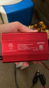
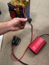
Hi, I have a 12v 100ah battery that I built. I have 300w inverter that use with it to charge varies things. I never had a problem till i tried to use a charger for a E-Skateboard. The charger output is 42v 8.0a. The invert i have does not have a built in fuse or terminals to hook up battery directly so i have a Noco 12v cigarette plug and i plug the inverter into that. The Noco has a 15amp fuse that blew as soon as i plugged it in, what is the problem? tia!


You are using an out of date browser. It may not display this or other websites correctly.
You should upgrade or use an alternative browser.
You should upgrade or use an alternative browser.
Help With Inverters
- Thread starter KnewB
- Start date
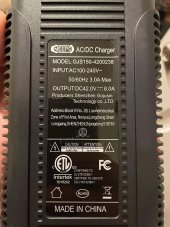
The charger is 42V at 8A. That's 336W. Your inverter only supports 300W. You need a bigger inverter for your charger.
A 15A fuse on a 12V circuit will only support 180W. The proper fuse size for a 300W inverter on a 12V battery is 30A. You should not try to use a plain 12V socket and plug. You should use 10AWG wire with the 30A fuse to connect the 300W inverter to the battery. But again, a 300W inverter is too small for a charger that needs 336W.
If you got a 400W inverter to support the charger then 400W on a 12V battery would need 8AWG wire and a 50A fuse.
Last edited:
mikefitz
Solar Wizard
- Joined
- May 28, 2020
- Messages
- 2,978
I have 300w inverter
The charger output is 42 V x 8 A = 336 watts. Since it wont be 100% efficient the input power will be higher, say 370 watts. The Inverter rated at 300 watts may not be able to provide this power, if it could, then the 12v input current would be at least 370 / 12 =30 amps. Up to now your loads have been quite low so there has not been an issue.The charger output is 42v 8.0a.
12v cig plugs and sockets are rated at 12 to 15 amps.
For safety you should always have a fuse at, or as near as possible, the battery positive terminal. The value of the fuse will depend of the expected current draw and the cable current carrying capacity. A internet search or a search in the resources will enhance your understanding of power in electric circuits and the need for protective devices, fuses and breakers, to prevent electrical fires and injury from molten metal when things go wrong.
Mike
Also keep in mind that with your current setup you are going from DC (battery) to AC (via the inverter) and back to DC (via the charger). That's pretty inefficient. You might want to look into getting a DC-DC converter that will boost the 12V-15V from the battery into the 42V needed by your E-Skateboard and avoid the DC->AC->DC conversion.
I've never heard of this, can you explain how that works?Also keep in mind that with your current setup you are going from DC (battery) to AC (via the inverter) and back to DC (via the charger). That's pretty inefficient. You might want to look into getting a DC-DC converter that will boost the 12V-15V from the battery into the 42V needed by your E-Skateboard and avoid the DC->AC->DC conversion.
thank you for the post i appreciate it! I'll omit the socket, get a bigger inverter, heavy wire and inline breaker.The charger output is 42 V x 8 A = 336 watts. Since it wont be 100% efficient the input power will be higher, say 370 watts. The Inverter rated at 300 watts may not be able to provide this power, if it could, then the 12v input current would be at least 370 / 12 =30 amps. Up to now your loads have been quite low so there has not been an issue.
12v cig plugs and sockets are rated at 12 to 15 amps.
For safety you should always have a fuse at, or as near as possible, the battery positive terminal. The value of the fuse will depend of the expected current draw and the cable current carrying capacity. A internet search or a search in the resources will enhance your understanding of power in electric circuits and the need for protective devices, fuses and breakers, to prevent electrical fires and injury from molten metal when things go wrong.
Mike
thank you, that cleared it up! was looking at a 500w inverter, so that would still require the same size wire and 50a fuse correct? is the math 500/12=42amp so i still get a 50 amp breaker?The charger is 42V at 8A. That's 336W. Your inverter only supports 300W. You need a bigger inverter for your charger.
A 15A fuse on a 12V circuit will only support 180W. The proper fuse size for a 300W inverter on a 12V battery is 30A. You should not try to use a plain 12V socket and plug. You should use 10AWG wire with the 30A fuse to connect the 300W inverter to the battery. But again, a 300W inverter is too small for a charger that needs 336W.
If you got a 400W inverter to support the charger then 400W on a 12V battery would need 8AWG wire and a 50A fuse.
Search for DC step up boost converters. Though it may be tough to find a good one that can handle your needs. You need one that can handle the 42V 8A output. Many let you adjust the output to a specific voltage. Harder will be one that can put out 42V and at least 8A while also supporting an input of 12V-15V (your LiFePO₄ battery will be variable within that range) and 30A. The high amp input makes it tough.I've never heard of this, can you explain how that works?
Ideally the math is 500W / 12V / 0.85 (efficiency factor) = 49A. So you need wire that safely handles 50A. Now you are up to 6AWG wire. Then 50A x 1.25 = 60A (roughly) which is the fuse size. So 6AWG wire and a 60A fuse for a 500W inverter on a 12V battery.thank you, that cleared it up! was looking at a 500w inverter, so that would still require the same size wire and 50a fuse correct? is the math 500/12=42amp so i still get a 50 amp breaker?
what about these fuses on the actual inverter, there is 2 40 amp fuses and this is a 500w inverter. Does that mean 80amps or they just redundant?Ideally the math is 500W / 12V / 0.85 (efficiency factor) = 49A. So you need wire that safely handles 50A. Now you are up to 6AWG wire. Then 50A x 1.25 = 60A (roughly) which is the fuse size. So 6AWG wire and a 60A fuse for a 500W inverter on a 12V battery.
Attachments
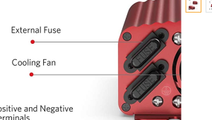
I can't tell from just that picture. Post a link to the actual inverter.what about these fuses on the actual inverter, there is 2 40 amp fuses and this is a 500w inverter. Does that mean 80amps or they just redundant?
I can't tell from just that picture. Post a link to the actual inverter.
I still can't tell exactly what the two 40A fuses protect. 12V at 40A is only 480W.
Despite the fuses in the inverter you should have a 60A ANL fuse at the battery then 6AWG wire to the 500W inverter. It's hard to tell for sure but I doubt the inverter has 6AWG wire with those battery clips. Hopefully it does.
Despite the fuses in the inverter you should have a 60A ANL fuse at the battery then 6AWG wire to the 500W inverter. It's hard to tell for sure but I doubt the inverter has 6AWG wire with those battery clips. Hopefully it does.
ok thanks. not worried about the wires, i'll make my own. Just making sure the inverter is up to the task. thank you!I still can't tell exactly what the two 40A fuses protect. 12V at 40A is only 480W.
Despite the fuses in the inverter you should have a 60A ANL fuse at the battery then 6AWG wire to the 500W inverter. It's hard to tell for sure but I doubt the inverter has 6AWG wire with those battery clips. Hopefully it does.
dang i just realized i only have a 50a BMS on this battery, Do i need to change that to a 60a as well if I'm going to use a 500w inverter or only if i see myself actually using over 50a?I still can't tell exactly what the two 40A fuses protect. 12V at 40A is only 480W.
Despite the fuses in the inverter you should have a 60A ANL fuse at the battery then 6AWG wire to the 500W inverter. It's hard to tell for sure but I doubt the inverter has 6AWG wire with those battery clips. Hopefully it does.
500W/12V=42A , The BMS should be ok.dang i just realized i only have a 50a BMS on this battery, Do i need to change that to a 60a as well if I'm going to use a 500w inverter or only if i see myself actually using over 50a?
When sizing the fuse, other things are considered.
As I showed back in post #9 you can only pull a max of 49A from the battery so the 50A BMS should be fine.dang i just realized i only have a 50a BMS on this battery, Do i need to change that to a 60a as well if I'm going to use a 500w inverter or only if i see myself actually using over 50a?
thank you!500W/12V=42A , The BMS should be ok.
When sizing the fuse, other things are considered.
gotcha thank you!As I showed back in post #9 you can only pull a max of 49A from the battery so the 50A BMS should be fine.
hey, just getting ready to build this but noticed my BMS wires are 10awg, is this a problem? thinking not because its on the negative side but not 100%.As I showed back in post #9 you can only pull a max of 49A from the battery so the 50A BMS should be fine.
continuous discharge current is 50a on the bms specs but how is that possible if 10awg is only rated for 30amps? again I'm guessing something to do with the Negative side? or cause the wires are short & silicone sleeves?
fyi i have a daly 50a 4s 12v bms with common wires.
Last edited:
Similar threads
- Replies
- 0
- Views
- 193
- Replies
- 32
- Views
- 670