


Hi,
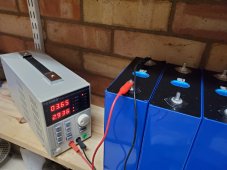
I've recently received 16x LF280K (Grade B). Individual cell voltages and polarities were all 3.27 - 3.28 volts with a multimeter. Yesterday I connected them in parallel for top balancing.
I bought a 30V 10A Bench power supply (https://www.amazon.co.uk/gp/product/B083BVGRLN/)
Set the voltage to 3.65V but only saw a very low charge current of a few amps.
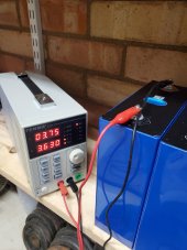
I was expecting the PSU to max out at 10A (or limit it to 8A), so I took apart the pack to test the cells individually.
I've connected each cell to PSU individually and they are only pulling 3A or less at a charge voltage of 3.65V
Could they be bad cells? or more likely what am I doing wrong?
Thanks for any advice!
I've recently received 16x LF280K (Grade B). Individual cell voltages and polarities were all 3.27 - 3.28 volts with a multimeter. Yesterday I connected them in parallel for top balancing.
I bought a 30V 10A Bench power supply (https://www.amazon.co.uk/gp/product/B083BVGRLN/)
Set the voltage to 3.65V but only saw a very low charge current of a few amps.
I was expecting the PSU to max out at 10A (or limit it to 8A), so I took apart the pack to test the cells individually.
I've connected each cell to PSU individually and they are only pulling 3A or less at a charge voltage of 3.65V
Could they be bad cells? or more likely what am I doing wrong?
Thanks for any advice!
")

