diy solar

diy solar

Help with question about wire derating

fafrd

Solar Wizard
Joined
Aug 11, 2020
Messages
4,188
My only previous solar install was an AC-coupled (Microinverter) based system, so wiring was pretty simple (240VAC, 2 current-carrying conductors).

I’m now in the thick of planning my first DC-coupled (off-grid) solar install and dealing with DC wiring and multi-conductor wiring for the first time.

I’m planning to use 4-wire 4AWG flexible metal conduit for the 2 home runs, and I’ve understood the presence of 4 conductors in the same conduit means they need to be derated to 80% (so 76A instead of 95A for 4AWG).

After further derating of 1.25 x 1.25 I can have a maximum of 48.64A of PV Isc max for each of these 4AWG home runs (which will translate to 4 parallel panels max per string in my case).

My dumb question is about the 10AWG PV wire running form the panels to the junction box. Is it the case that anytime there are 4 conductors (2 panels) running in parallel for more than 24” (~2/3rds panel width) those 10AWG conductors need to be derated to 80% (32A instead of 40A)?

If so, that would mean a maximum of 20.48A of Iscmax, meaning only a single panel per 10AWG wire for the panel class I am looking at.

And if I use a Y connector to join 2 panels in parallel, I’ll need to step up to 8AWG which will be be able to carry 35.2A of Iscmax (3 panels) if the cable doesn’t follow the same path as other conductors for over 24”, or only 28.16A of Iscmax (2 panels) if the cables follow the same path as other conductors for over 24”?

I’m trying to understand how the 80% derating rule for ‘raceways’ with more than 3 current-carrying conductors applies to the MC4 PV wiring tied to the racking system and whether installers go to the trouble of configuring wiring to avoid more than 24” of overlap for cases where that are using 8AWG to carry a full 35.2A rating of Iscmax.

For example, it’s generally a good idea to tie PV wiring to the inside of the rails of a racking system, but I don’t believe it is a requirement.

If one pair of current-carrying conductors is tied to the inside of the rail and a second pair of current-carrying conductors is tied to the outside (or underneath) of the same rail, does that allow those conductors to be considered ‘not in the same raceway’ and the 20% derating does not need to be applied?
 
Cable de-rating is a very complex subject and it is far more complex than just applying a percentage. There are many factors:
* is the wire in conduit
* How far off the roof is the conduit
* How many wires are in the conduit
* What is the temp rating of the breakers the wire is tied to.

Every time I go to do the de-rating I have to go look up the process again. On top of that, the calculation for the current requirements for PV wiring is somewhat complex. You may want to review this resource:


At the very end of the resource there is a page that gives a brief nod to de-rating but does not describe how to do it.

This video talks through the process for de-rating....You will probably have to watch it several times to understand what she is saying.
 
If the MC cables were tightly bound as a bundle, derating for 4 or more conductors would apply. Inside a conduit would do the same thing.
If inside a very large conduit or channel, obviously would not restrict heat dissipation as much although code doesn't give any credit for that.
If secured to rails and somewhat spread apart then I wouldn't worry about "bundling" retaining heat.

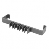
I've seen various devices to secure individual MC cables. that would let them hang individually in the air.

1613689164252.png


Considering that 10 awg 90 degree single conductor in free air has ampacity 55A, it's annoying to have a 30A limit imposed by code.
 
Cable de-rating is a very complex subject and it is far more complex than just applying a percentage. There are many factors:
* is the wire in conduit
* How far off the roof is the conduit
* How many wires are in the conduit
* What is the temp rating of the breakers the wire is tied to.

Every time I go to do the de-rating I have to go look up the process again. On top of that, the calculation for the current requirements for PV wiring is somewhat complex. You may want to review this resource:


At the very end of the resource there is a page that gives a brief nod to de-rating but does not describe how to do it.

This video talks through the process for de-rating....You will probably have to watch it several times to understand what she is saying.
That was a very helpful video - thanks for the link. I knew most of that but had not been aware that fuse temperature rating applies to wire as well, so again, thanks.

There were only two strings in that example, but no mention was made of derating the use-2 wires because of more than 3 current-carrying conductors flowing parallel paths to the combiner box over more than 24”, so if I take that as a reference, it implies that the current-carrying-conductors-in-conduit adjustments don’t need to be applied to PV wires in air tied to parallel paths for over 24”.

But I would appreciate a more definitive confirmation of that, if possible...
 
NEC says,

"NOTE 4:
Where the number of current-carrying conductors in a raceway
or cable exceeds three, or where single conductors or multiconductor
cables are stacked or bundled longer than 24 inches
without maintaining spacing and are not installed in raceways,
the allowable ampacity of each conductor shall be reduced as
shown in the following table:

4 thru 6 80%"
 
If the MC cables were tightly bound as a bundle, derating for 4 or more conductors would apply. Inside a conduit would do the same thing.
If inside a very large conduit or channel, obviously would not restrict heat dissipation as much although code doesn't give any credit for that.
If secured to rails and somewhat spread apart then I wouldn't worry about "bundling" retaining heat.
That’s exactly the confirmation I was seeking - thamks
I've seen various devices to secure individual MC cables. that would let them hang individually in the air.


View attachment 37541
Thanks - that looks like a perfect solution to address the concern I had.

Considering that 10 awg 90 degree single conductor in free air has ampacity 55A, it's annoying to have a 30A limit imposed by code.

Strictly speaking, you mean 35.2A, correct?

And getting that 35.2A rating means having fuses rated for 90F (and no additional temperature derating due to proximity to roof), right?
 
NEC says,

"NOTE 4:
Where the number of current-carrying conductors in a raceway
or cable exceeds three, or where single conductors or multiconductor
cables are stacked or bundled longer than 24 inches
without maintaining spacing and are not installed in raceways,
the allowable ampacity of each conductor shall be reduced as
shown in the following table:

4 thru 6 80%"
Thanks. So you need to use a solution to ‘maintain spacing’ such as the one you linked to to avoid that additional 20% derating...
 
Apparently something due to fuse temperature rating. Wires do fan out in a box before reaching fuse or breaker, but I think breaker terminals are only rated 60 or 75 degrees. Not sure if this gets carefully obeyed. But the 12 awg 20A and 10 awg 30A limit keeps it down to 60 degrees.

Where did 35.2A come from?
10 awg we're required to limit to 30A fuse (except wires inside an appliance can have higher current.) Single or bundle, 60 degree to 90 degree insulation, ampacity ranges from 30A to 55A. But 30A is max allowed. So lots of derating before less than 30A fuse is required.
 
Thanks. So you need to use a solution to ‘maintain spacing’ such as the one you linked to to avoid that additional 20% derating...
I think cable ties occasionally, and the hanging cables would maintain spacing except for those brief bundles. Only if you pulled them straight might they block air flow between.
 
Apparently something due to fuse temperature rating. Wires do fan out in a box before reaching fuse or breaker, but I think breaker terminals are only rated 60 or 75 degrees.
So a breaker in the basement at 65F but only rated for 75F means that the entire 4AWG home run coming from attic to basement is only rated for 75F?

Are there any fuses rated for 90F?

Not sure if this gets carefully obeyed. But the 12 awg 20A and 10 awg 30A limit keeps it down to 60 degrees.

Where did 35.2A come from?

55A / 1.25 / 1.25 = 35.2A

10 awg we're required to limit to 30A fuse (except wires inside an appliance can have higher current.) Single or bundle, 60 degree to 90 degree insulation, ampacity ranges from 30A to 55A. But 30A is max allowed. So lots of derating before less than 30A fuse is required.
Where is that from?

I’m interested in max ratings for 10AWG and 8AWG PV wire...
 
Not Fahrenheit. Insulation and components rated 60C, 75C, 90C
I think the wire could be in a bundle in the attic (if attic not above 30C) with ampacity of bundle rated based on 90C insulation. But single wire going into fuse holder should have current within limits for single conductor rated 75C if that's the fuse holder rating. So wire isn't hotter than 75C at that point.

Isc of panels x 1.25 x 1.25 should be below 30A for 10 awg.

This chart has a note ** 10 awg maximum 30A

 
Not Fahrenheit. Insulation and components rated 60C, 75C, 90C
Sorry, my bad. Yes, degC, not degF.

I think the wire could be in a bundle in the attic (if attic not above 30C) with ampacity of bundle rated based on 90C insulation. But single wire going into fuse holder should have current within limits for single conductor rated 75C if that's the fuse holder rating. So wire isn't hotter than 75C at that point.

So as long as the fuse holder is located in an area (basement) never exceeding 75F, no additional temperature rating needed - OK for the same 4AWG wire to be above 75F in attic and below 75F where connected to fuse holder.

Where are you getting the 30C (86F) attic temperature limitation from?

Isc of panels x 1.25 x 1.25 should be below 30A for 10 awg.

This chart has a note ** 10 awg maximum 30A

Hadn’t seen that - thanks.
 
Where are you getting the 30C (86F) attic temperature limitation from?

Same chart.

"Note 5:
For ambient temperatures other than 30°C, multiply the allowable
ampacities by the appropriate factor shown below:"

Attic is an example of a place where temperature derating probably applies. But the fact a 10 awg 90C wire has ampacity 40 means it can be in hotter environment before derating drops it below 30A.
OK, so standard temperature derating based on the hottest temps reached in my attic.

So I’ll need to derate to 96% if I exceed 30C (86F) but not 35C (95F) or debate to 91% if I sometimes exceed 35C but never 40C (104F).

That’s still a lot better than derating the entire cable from 90C to 75C...
 
For wires fanned out to fuse holders, I'd use the single wire ampacities and derate if needed for local temperature:

If these ampacities apply as long as wires are separated that provides a lot of head-room.

10 AWG from panel into MC4 fuse holder is 41.8A derated for 55C (capped at 30A), so I can combine 2 panels into 10 AWG PV wires at an exceedingly safe temperature of 55C (131F).

And if I need more than 2 panels combined into a single PV wire, 8AWG derates to 60.8A @ 55C (131F), meaning 4 and even 5 panels (in my case).

The MC4 fuse holder and MC4 Y-connector all seem to be rated for high temperatures but I need to check into that before combining more than 2 panels into wires.

I’m looking at an 8-panel system so running 4 pairs of 10AWG wires into my under-panel combiner box seems like the easiest way to go...

All of the tables I’ve seen regarding ‘wire distance over roof’ seems only to apply to wires or conduit exposed to sunlight, so since I’m running all wires under panels, I don’t believe any of that applies to me (even though my wires will be tied to rails >3” above roof...).

But if I want to be conservative about attic temperature, I should either move to 2 home runs of 4/2 MC or step up to 3/4 MC (which ends up being cheaper).

And another question as I mull my options: is there any requirement that the + and - wires be run in the same conduit?

If I run 3 + wires from strings in one conduit and 3 - wires from those 3 strings in another conduit, I can avoid the 20% derating for >3 wires without needing to run 3 separate conduit runs - is that an option?
 
And if I need more than 2 panels combined into a single PV wire, 8AWG derates to 60.8A @ 55C (131F), meaning 4 and even 5 panels (in my case).


And another question as I mull my options: is there any requirement that the + and - wires be run in the same conduit?

If I run 3 + wires from strings in one conduit and 3 - wires from those 3 strings in another conduit, I can avoid the 20% derating for >3 wires without needing to run 3 separate conduit runs - is that an option?

MC connector rated for 30A, so to make use of 8 awg, a Y connector would have to have one connector cut off, then splice to long 8 awg wire for the home run. I just have MC pigtails coming out of a junction box.


For AC we certainly want them in the same (ferrous) conduit. For DC it doesn't matter in a practical sense. Not sure what's in the code on that.
If you parallel all the strings then you just have 2 wires in the conduit. It ends up meaning less copper to carry the same current.
 
MC connector rated for 30A, so to make use of 8 awg, a Y connector would have to have one connector cut off, then splice to long 8 awg wire for the home run. I just have MC pigtails coming out of a junction box.
You can purchase 8AWG MC4 cables and connectors rated for 50A - they are just more expensive and you have to be careful about where you get them from (BourgRV is one source, I believe).

And instead of an Yconnector with pigtails, I have a solid Y which is also rated for 50A.

So I was going to cut the end off of an 8AWG MC4 PV wire (or use 8AWG MC4 connectors rated for 50A) to make long pigtails coming out of the Soladeck junction b

For AC we certainly want them in the same (ferrous) conduit. For DC it doesn't matter in a practical sense. Not sure what's in the code on that.
I believe I read somewhere that bundling + cables from multiple strings in one conduit is OK (with -s bundled in another conduit) is OK, but I’d like to confirm whether code says anything on that.

Instead of trying to do 2 4P strings, it’s going to work much better to have 3 3P strings (or 2 3P strings and 1 2P string).

If you parallel all the strings then you just have 2 wires in the conduit. It ends up meaning less copper to carry the same current.
Yes, the strings are all in parallel, so getting to two wires would be possible (and great) but may just be prohibitively more expensive (for the array size I’m planning for).

I’m looking at a 2700W array composed of 8 450W panels w/ Iscmax 11.75A.

So total Iscmax for the entire array is 94A and after derating by 125%^2 comes to 147A. Add in further 87% derating for temps of at least 107F (41.7C) and I need a wire that can carry 170A - out of reach.

Do that’s why I was looking at 2 4P strings carrying ~85A each (after derating), meaning 4AWG could work. But if I use 4/4MC, the 4 conductors in the conduit force another 80% derating, bringing me to 106A and forcing me to 3/4MC.

So I could get by with 3/4MC which would run me $300 but would only be rated for attic temps of up to 45C (113F) which is only 6F higher than hottest recorded temp of 107F.

If I want to plan for temps up to 50C (122F) that pushes me to 2/4MC which would run me $400.

Alternatively, I forget about 4 panels per string and look at 3 3P strings rather than 4 2P strings.

I can carry 3 strings on 2 6/3 conduits which will cost me $155 and be rated for up 55C (131F), way hotter than I’ll ever need to worry about in my attic.

Cheaper AND safer, it’s pretty much of a no-brainer, really.

So now I’m looking at running 3 3P arrays to the junction box which will mean running 2 1/2” conduit on the roof (exposed to sun).

I think I’ve understood that the new rules mean no additional temperature derating as long as you are at least 0.75” above the roof (and I’ll be closer to 3”).

So I think I’m just about all set but just have a few questions (which I’ll put in a second post since I just hit ‘post’ on this one by mistake).
 
I’ll have 8AWG PV wire tied to the 6AWG 6/3 MC in a Soladeck junction box. I’m interested in any advice in the best way to make these junctions but am considering DIN terminal blocks which are rated for 60A up to a temperature of 120C.

Is there any temperature derating needed for a terminal block l like this?

Are there other ways to form junctions of PV strings carrying these levels of current that are better?
 
I’m looking at a 2700W array composed of 8 450W panels w/ Iscmax 11.75A.

So total Iscmax for the entire array is 94A and after derating by 125%^2 comes to 147A. Add in further 87% derating for temps of at least 107F (41.7C) and I need a wire that can carry 170A - out of reach.

Do that’s why I was looking at 2 4P strings carrying ~85A each (after derating), meaning 4AWG could work. But if I use 4/4MC, the 4 conductors in the conduit force another 80% derating, bringing me to 106A and forcing me to 3/4MC.

??

Are you putting 8, 450W panels all in parallel, and that's how you get to 94A?
My 2700W series strings are about 7A, run in 12 awg.
 
Back
Top