


Just when I was thinking I finally see light at the end of the tunnel...Key assumption is that bypass diodes work, don't fail if continuously carrying Imp. Some brands/models can't handle that.
What happens when… bypass diodes fail?
Series troubleshooting: Bypass diodes fail regularly, either because they do not have a high enough power rating or because they are overloaded due to nearby lightning strikes. With the following hypothetical, but realistic case pv magazine starts a series which aims to make the estimation of...www.pv-magazine.com
Issues with bypass diodes
As the latest in its investigation into quality issues at pv plants, Heliolytics looks at failure modes in bypass diodes - and what can be done about them.pv-magazine-usa.com

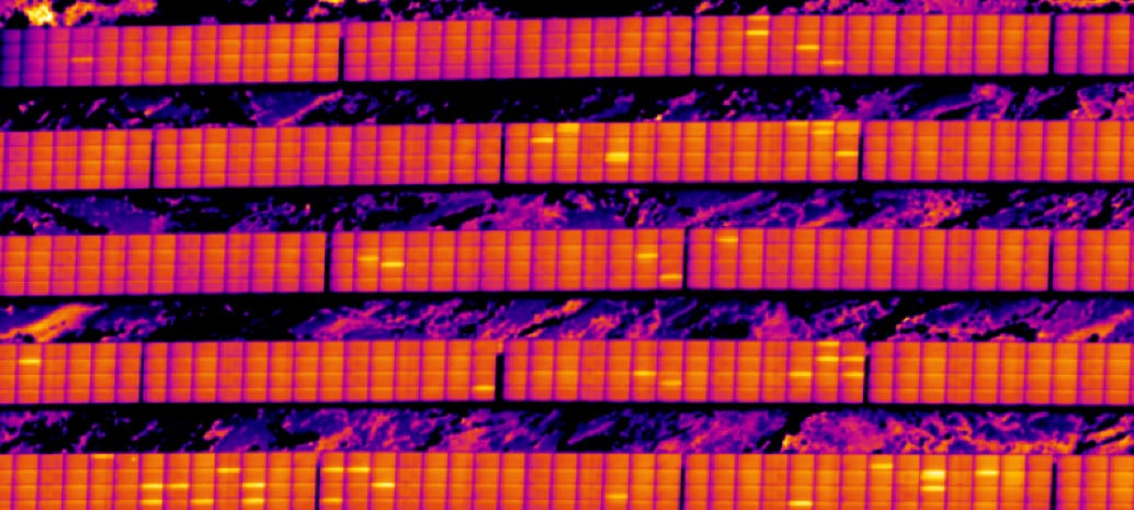
Fig. 6. The root cause of top #1 failure mode (burnt bypass diode)
Download scientific diagram | The root cause of top #1 failure mode (burnt bypass diode) from publication: The Reliability Investigation of PV Junction Box based on 1GW Worldwide Field Database | The reliability of junction box plays the critical characteristic in PV development. We perform the...www.researchgate.net
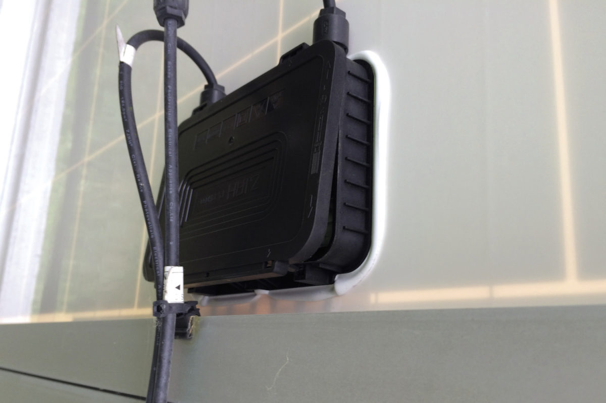
These are Trina panels, and 72-cell so aimed at the insustrial market, so lower-quality diodes are not a huge concern.
But because of my shading, bypass diodes will be exercised until about noon daily (if I allow it), so if even high-quality diodes can be a point of failure from regular use, maybe I should start thinking about a parallel array again.
With a parallel array, shaded half-panels will just not contribute to the current being output and bypass diodes will pretty much never be activated (SCC will be locked at Vmp_panel from first light to last light).
I suppose I could always rely on my warranty and switch to a parallel string if I get repeated failures...


