diy solar

diy solar

Help with tripping WFCO tripping

rhinosun

New Member
Joined
Apr 4, 2021
Messages
26
I have a GO Power! TS-30, the Gen legs are fed from a invertor. I also have the hot and neu for shore power. Everything seems to work fine, however, if I am running on 12v / solar the WFCO WF-8735 trips. I have to turn the breaker (this is the same breaker that powers the WFCO fan and charge when on shore) off for the WFCO to be able to run the 110 plugs without tripping when on solar.

I followed this -


Can someone explain to me if this should be happening? Or what I should do to correct the situation?
 
I think that you DO need to interrupt the flow into the WFCO Converter Section when you want to run 120V from your Inverter. This is because it will fall into a loop: 120V is made available into the "30A" breaker from the transfer switch, and the 120V "hot" bus becomes able to provide power through the 15A breaker, into the Converter Section. But that same 120 Volts, coming from the Inverter, has pulled down the "12V" Voltage -- to a point where the WFCO Converter Board wants to charge the battery "hard" (it's no longer operating in "float mode").

That in turn puts more load on the Inverter, which attempts to pull more power from the batteries - with approximately 15% power loss in the Inverter (if it's a fairly good one), plus another 15-20% within the WFCO, attempting to converter right back to 12V. The WFCO rapidly ramps up to maximum output, the fan comes on, and the power-loosing loop runs indefinitely.

My non-WFCO "Power Converter Board" sits on a dedicated 15A Breaker, separate from other Trailer circuits. Whenever I plan to turn on the Inverter, I simply walk over the WFCO panel and disable the Converter's Breaker by hand. (It's actually a PD replacement section, sitting within the older WFCO case which still runs my 120-VAC and 12-VDC Power Distribution.)

But, if you're willing to do some wiring work and buy a pair of Relays, that could be automated by using a "Sensing Relay" (120-VAC Coil) along one of the Transfer Switch Input cables, and taking its "power" load terminals (which may be only 12-VDC) to drive another Relay. This load terminals of this 4-pin secondary relay are placed along the 120V "hot" wire from out of the 15A breaker, into the Converter Board.

For the case of a secondary Relay "Normally Open", the "Sensing Relay" would be placed along the "shore input". Active shore power causes the secondary Relay to close, allowing the Power Converter Board to operate. For the case of a secondary Relay which is "normally closed" (they are harder to find) the "Sensing Relay" would be placed on the 120V inverter's input to the transfer switch, and the presence of power on the 120V Inverter Cable would turn the secondary Relay "off" until Inverter power disappears.
 
I believe the inverter is powering the WFCO converter. The WFCO needs to be turned off. Could be rewired to only get power from the utility cord if you are so inclined.
 
I believe the inverter is powering the WFCO converter. The WFCO needs to be turned off. Could be rewired to only get power from the utility cord if you are so inclined.
My point exactly. But the Utility cord, IMO, should go only into the Transfer Switch (with maybe a TINY amperage "Sensing Relay" added), and then directly to the 30A main breaker via the Transfer Switch. No earlier "break-out" load circuits bypassing the 30A Breaker, not even if they have their own fuses or circuit breakers.
 
Go Power has a transfer switch that breaks out a 15 amp connection to power the converter from only the utility cord.
Easy mode to most 30 amp TS.

https://gpelectric.com/products/30-amp-pre-wired-transfer-switch/


GP-TS_Drawing.jpg
 
Nice product, although total "shore power" can exceed the limiting circuit breaker (usually 30A) at the "AC Panel" connection. If shore power is separately fused, or can handle the sum of "AC Panel" plus "Charger" current, this is a perfect product. My scheme is VASTLY more complicated.
 
Yes if the cord was plugged in using a standard 30-50 adapter the cord could be subject to more than 30 amps.
 
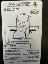
Hey all - Thanks for the replies. The above diagram is what I have going on. When I am on battery, I have the invertor wired into the transfer switch so it will power my WFCO. That way I can use my 110 plugs to watch TV to fall asleep (haha).

I misspoke also, I meant to say. with the WFCO breaker on, the inverter trips and beeps. It’s just a small little invert - Samlex PST 300 12.

With the WFCO breaker off, all is fine or so it seems.
 
Do you mean the wfco converter breaker or the wfco distribution panel ac master breaker?
Its the breaker that powers the Fan and the circuit board. I guess that would be the converter breaker?? I am not 100% sure.
 
Its the breaker that powers the Fan and the circuit board. I guess that would be the converter breaker?? I am not 100% sure.
That sounds like the converter.
The converter turns alternating current into direct current.
You inverter turns direct current into alternating current.
I suspect that you have power loop between them.
Others have said as much earlier in the thread I think.
Is the inverter ac connected to the ac distribution panel?
Please take a picture of the ac connections to your inverter and post here if unsure.
Also take a picture of your ac distribution panel with the cover open and post here.
 
The inverter out, goes to the Gen in on the GP-TS. I will take some pics when I get back. About to run out.

I have shore power in, to a 30 AMP breaker on the WFCO, then a 15 amp runs the 110 plugs, then another 15 amp, which we believe is the converter. I do use all the 12v circuits on the WFCO also - FYI.

Thank you taking the time to explain everything
 
Rhinosun,
if you look a bit closer at the wfco you will find a main ac breaker and an AC breaker for the 12V converter/charger. The 12V converter is also the fan you mention. That fan should only be needed when using the 12V converter.
i see your dilemma, when you shut off the converter, any 12V device in the trailer is running off (depleting the battery) along with the inverter load depleting the battery. The AC side of the WFCO will happily utilize any AC it gets from your inverter. Be sure to turn the fridge and water heater onto propane, otherwise the fridge refrigerant heater will consume a lot of Ac and in turn, battery power. Also, remember, the fridge propane circuit uses a bit of 12V power for its control side.
 
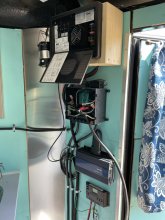
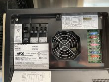
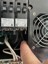
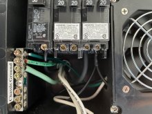
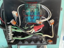
Here are some picture. So, I should keep doing what I am doing and turn off the last 20amp breaker, that is the converter/charger (my finger pointing to it).

From top to bottom.
WFCO
GP-TS
Samlex invertor
Charge controller (testing solar) 100W

IMG_4448.jpg

IMG_4449.jpg

IMG_4450.jpg

IMG_4451.jpg

IMG_4452.jpg
 
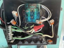
Also, the wire nut (red) is either for 30 amp or 120v. I just tied the inputs together.

Just so I could have options at the camp site.
 
I can't see the connections to the transfer switch but It should be wired similar to the diagram in post#5.
The converter should be wired the same as the "charger" in the diagram.
Unless you have some other way to charge your battery and power your dc distribution panel, then it can just be disabled.
 
Last edited:
I never understood how the charger works. I thought it was built into the WFCO and somehow charged when I was on shore power. Not an external charger. Seems that way, my battery has always kept charge so far. Just to be clear I have the WFCO-8735-P. I think that diagram is a tad different then what I have.
 
The output from the Samlex (invertor) is going to the input (pictured in red). The inverter is just tied onto the Pos and Neg of deep cycle battery.


Edit.jpg


IMG_4316.jpg
 
So, I should keep doing what I am doing and turn off the last 20amp breaker, that is the converter/charger (my finger pointing to it).
Yes, that works - although your relevant "20A" circuit breaker is definitely branched into two "downstream" circuits (one leading to your regular plugs, presumably through a GFI outlet, and the other leading into WFCO's Power Converter Board. Your fix, to separate the regular 120V outlets from the WFCO, is extremely simple:

Shut off the main 30A breaker. In addition, I recommend that you pull the 30A cord and make sure the Inverter is off, just to be double-sure that no 120-VAC power is reaching that bus. Then, use your volt meter to verify zero "AC" voltage difference between "chassis ground" and the 30A Breaker input lug. You're now triple sure to be working only with unpowered wires.)

Leave the breaker with the bigger 20A wire (leading to your air conditioner) undisturbed. But, using a #2 square drive screwdriver, loosen your target breaker screw (the last one) and pull out the wire with the "branch" happening about 1/2" down. With that common wire now loose, CUT the wire at the place where the two wires become joined. Strip the now separate ends (stripped length a bit less than 3/8"). Put the smaller wire (the wire for Converter) back into the same Circuit Breaker.

Move the slightly bigger wire (the wire for 120v-outlets) over to one of the empty slots on the first 20A breaker.
- - - -
That's in the short term. In the long term, I recommend that you install a SMALLER breaker (15A x 2) in place of the right-most dual-20A breaker, because your Inverter shouldn't ever need to draw even 15A. And your regular outlets, unless they are T-slotted for 20A appliances, shouldn't support more than 15A either. It also looks like your "downstream" wiring is small - and possibly 14-AWG, rather than 12-AWG. You must never allow "20A" on 14-AWG wire.

After buying that breaker, you again disconnect all input power sources and flip the 30A breaker to "off", and retest. Move the air conditioner "Hot" wire over to one of the left-side Circuit Breaker terminals, And put your remaining smaller wires (the Converter wire and the Outlet wire) into the new 15A breaker ports.

Here's that Breaker, over at Amazon. https://www.amazon.com/Siemens-Q1515-120-Volt-Breakers-breakers/dp/B00002NB0L/ It is sometimes also an in-stock item at Lowes, and at Home Depot.
 
Last edited:
Back
Top