diy solar

diy solar

Heltec BMS' (up to 350A) with Active Balancing & Independent Active Balancers

I don't know ... I haven't had to return anything to them .... but, isn't that the risk we take when buying any product that ships from China?
Of course, but we have seen many cells replaced at the suppliers expense (including shipping) and the supplier never wants the damaged/defective products returned.
The last problem I remember that looked like it may have been a BMS problem .... I'm pretty sure that @Sipma02 said after exchanging emails, Jason had agreed to send him a new BMS.
As it should be. I think all the Chinese suppliers need to be clear about the terms of their warranty and stand by it. Good support is part of the equation whether ordering from China, the USA or the north pole. And taking good care of customers goes a long ways towards the suppliers reputation.
 
I have a Chargery and I have to say I'm extremely pleased with it - and I VERY much like it having a remote control and display screen I can put at the end of a 80 foot phone cable to see whats going on while in the main house and not having to find my phone or fire up a computer.

It uses external relays or SSRs for separate control of charging.

Personally I wouldnt trust chinese mosfets of unknown provenance with anything more than 40 amps, maybe even down to 30. I'm using Gigavac contactor relays on both the charge and discharge current paths, the discharge is a 400A contactor and the charge is a 150A contactor and they barely get above ambient temp. They use about 8 watts each to stay energized and have integrated flyback diodes. I can't recommend gigavac enough, they're a awesome value.

I also like knowing that if it fails it fails in a safe condition and the contactors open. Mosfets fail closed so you could be in a situation where you have no ability to do a emergency over/under voltage shutdown only to discover the hard way that the mosfets failed.

There's a reason industry uses contactors for high amperage loads and its a pretty good one. The only time we use SSRs is to drive contactors.
 
I don't know ... I haven't had to return anything to them .... but, isn't that the risk we take when buying any product that ships from China?

The last problem I remember that looked like it may have been a BMS problem .... I'm pretty sure that @Sipma02 said after exchanging emails, Jason had agreed to send him a new BMS.

Just jumping in because @Bob B tagged me, I didnt read the rest of the discussion...

... Yes, Jason was happy to send me a new BMS. I will have to ship him back my old one, not sure how much that will cost yet. I'm still testing the replacement to see if it will work. Overall, I love the adjustability and customizability of the Chargery platform. If it proves to be reliable, I'll love it that much more!
 
Hmmm.. Debating Pros & Cons of relays. Well If they are good enough for EV's which absolutely quality as High Amp use, good enough for me.
I used the original Electro-Mechanical Relays at first... power hogs, then the TE/Kilovad EVE200's which were much better as well as others through the testing with the Dongya Energy Savers (darn good relays and way cheaper) and then onto the SSR's which are terrific.

BTW, I AM the Original Poster of this thread... I posted this because Heltec has the Active Balancing capability with their BMS' but also as separate devices as well and is one of the few to be "Known Good" for their Active Balancers. I do NOT Own a Heltec BMS or Active Balancer (I use QNBBM Active Balancers).

I use my Chargery BMS8T's, they work perfectly fine and with the latest flash update, plus ISO Board & External power interface board, the BMS' are quite settled and performing as they should be. I am looking forward to the release of the Next Generation of Chargery with incorporated Active Balancer and more and will likely transition to those and finalize my solar system.

Side Note: I am not following many topics as it simply became "overload" with volume, and to be honest, a lot of repetitive (too much) round & around a subject (the cell compression threads for example), so I am peeking into threads & responding when "pinged".
 
Chargery was high on my list. But when I decided to buy people were complaining too much so I gave the Heltec a try and liked it.
If someday I find I need more amps than my Heltecs can handle, I will have to make some changes.

High amps = high cost and more danger.
I don't know if I will ever use high amps but if I do, I'm going to work my way there slowly.

I'm having enough trouble trying to figure out how to deal with short circuit amps.
 
Side Note: I am not following many topics as it simply became "overload" with volume, and to be honest, a lot of repetitive (too much) round & around a subject (the cell compression threads for example), so I am peeking into threads & responding when "pinged".
I've been un watching a lot of threads too. If you don't want to hear what I have to say, See ya
And the same if I don't want to hear it anymore.
 
Inspecting my failed BMS, it looks like an entire P- copper busbar was poorly-soldered - I can slip a piece of paper under it most of the length. So whether that could have led to the high resistance and heat buildup I experienced or not, I can’t say, but it certainly didn’t help.
Also, it appears that particular unit may have had a manufacturing defect (P- bus bar only soldered at very ends, largely unsoldered to landing pad on board.

The problem was definitively caused by this.

Because of that the current was not shared correctly between the MOSFETs so only a few of them did all the work while the others wren't doing anything.
 
If you measured 80mV voltage drop through your Heltec BMS discharging 80A, that’s all the confirmation I need that the BMS I received was defective.

Resistance actually the #7 wires I don’t understand - didn’t you measure directly on the P- and B- terminals of the BMS? Is your BMS encased in plastic so you had to resort to measuring at the lugs connecting to the battery - terminal and - cell terminal?

If your #7 wires came preassembled and you can estimate length for me, I can estimate what number of those 80mA you you measured were across both wires...
On the JK 200 amp smart BMS, the P- and B- leads are each a pair of #7 AWG wires that are pre soldered to the board inside. The case is a cast aluminum enclosure with the high current wires coming out each side. On the battery side, I shortened them to about 5 or 6 inches and they connect to a buss bar where the cables come from my battery bank. My battery bank feed to that buss bar is a pair of #2 AWG cables. On the output side of the BMS, I shortened the leads again, to about 5 inches, and spliced them to a 2/0 cable for another 8 inches or so where it connects to my battery bank output buss bar. My measurement was between the 2 buss bars. I think I have a picture showing this.
IMG_2411.JPG
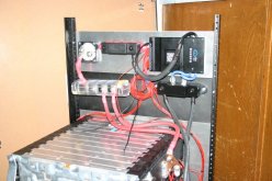
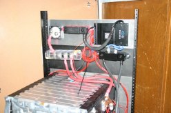
This was before it was all finalized and installed in the cabinet. So my voltage drop measurement was taken between the 2 black buss bars. So it included the drop of the pair of blue wires, and then the 2 thin black wires and the 2/0 extension to the second buss bar. The splice is a heavy wall copper sleeve crimped around the 3 wires for a full inch. I did not try to measure at the board. It seems a bit sketchy to power up the board without the case on it, especially since the cast aluminum case is the FET heat sink. The wires are well fanned out onto the PC board, which has a copper metal plate also soldered over the current carrying trace. The buss bar on the left has marine style fuses for the 2 strings of batteries, and mounted on the cabinet, is a Class T fuse for the entire bank after the shut off switch.
 
On the JK 200 amp smart BMS, the P- and B- leads are each a pair of #7 AWG wires that are pre soldered to the board inside. The case is a cast aluminum enclosure with the high current wires coming out each side. On the battery side, I shortened them to about 5 or 6 inches and they connect to a buss bar where the cables come from my battery bank. My battery bank feed to that buss bar is a pair of #2 AWG cables. On the output side of the BMS, I shortened the leads again, to about 5 inches, and spliced them to a 2/0 cable for another 8 inches or so where it connects to my battery bank output buss bar. My measurement was between the 2 buss bars. I think I have a picture showing this.
View attachment 34691
This was before it was all finalized and installed in the cabinet. So my voltage drop measurement was taken between the 2 black buss bars. So it included the drop of the pair of blue wires, and then the 2 thin black wires and the 2/0 extension to the second buss bar. The splice is a heavy wall copper sleeve crimped around the 3 wires for a full inch. I did not try to measure at the board. It seems a bit sketchy to power up the board without the case on it, especially since the cast aluminum case is the FET heat sink. The wires are well fanned out onto the PC board, which has a copper metal plate also soldered over the current carrying trace. The buss bar on the left has marine style fuses for the 2 strings of batteries, and mounted on the cabinet, is a Class T fuse for the entire bank after the shut off switch.
Nice GXMnow. Is the class T fuse between the busbar and the switch? I don't see the switch.
 
The problem was definitively caused by this.

Because of that the current was not shared correctly between the MOSFETs so only a few of them did all the work while the others wren't doing anything.
I just inspected more closely and I can literally slide a piece of paper all the way under the bus bar and see it poke out on the other side. These is only any solder / attachment over the final ~5mm at either end, so the full 80A was running through a copper busbar that is 15mm wide and maybe 0.75mm thick for a distance of over 50mm.

That’s a cross-section of ~11mm^2 or about 7AWG which has a resistance of only 1.63 mOhms / 1000mm or just over 0.08 mOhms over a 50mm length.

That alone contributed ~0.5W of heat that should not have been there at 80A but I suspect you are correct that the fact that current was distributed to the MOSFETS only from either end of the busbar and not along it’s entire length resulted in the first and/last MOSFET taking the lion’s share of the current and overheating.

Lesson learned for me - I will carefully inspect any high-current large-area solder joints to copper busbars carefully before stressing them with high current.

I have a second brand-new unit of the same BMS and will retry my 80A stress test once I have rebuilt my battery with grub screws.

China is on Holiday now, but from the initial dialog with Heltec, I’m hopeful they will acknowledge this obvious manufacturing defect and replace the fried BMS.

So many lessons to learn in this DIY LiFePO4 world...
 
Lesson learned for me - I will carefully inspect any high-current large-area solder joints to copper busbars carefully before stressing them with high current.

Yep, that's one of the problems with chinese devices, you need to do the QC yourself.

Also, your adventures made me realise they didn't even tested the BMS at high current during QC which is kind of one of the few most important things to check... is there even QC?


China is on Holiday now, but from the initial dialog with Heltec, I’m hopeful they will acknowledge this obvious manufacturing defect and replace the fried BMS.

Good ;)
 
Last edited:
I think it's just bad soldering + bad QC. Else all their BMS would fail very quickly if that was the intended design...
 
It almost sounds like they are trying to use that bar as a shunt of some kind ?
If that question is addressed to me, no, it’s a manufacturing flaw.

On the other never-used identical unit, all for copper busbars (one per side for B- and one per side for P-) are well-soldered to the landing pad on the main board over their entire width and length.

On the defective BMS, 3 of those 4 bus bars are soldered down just as well but the bottom P- busbar is not soldered to the board over most of it’s area (entire width over most of the length).

I don’t see any signs of solder over that unsoldered area and can slip a piece of paper all the way under the copper busbar do it protrudes on the far side.

However the solder was applied to the board, looks like it failed to apply any there. Both ends are soldered so it’s just the large continuous area under the central area of the busbar where it is unsoldered and floating.

Of course it was that one defective P- busbar that I (unknowingly) selected to bolt my ground lug to (so all the current went through that line busbar).

I’ll switch to dual wires contacting both busbars of P- and B- from now on.

And as I stated earlier, while all of the 80A flowing through that one ~#7AWG busbar added a few Watts versus what it would have been with proper soldering, that probably wasn’t enough to cause the failure I experienced which was more likely caused by the uneven distribution of current to the array of power transistors so the the outermost-one took the lion’s share of the 80A and overheated (over the course of an hour).

The fact the two identical units are clearly different in that area is blear indication of a manufacturing defect...
 
Nice GXMnow. Is the class T fuse between the busbar and the switch? I don't see the switch.
In this image
IMG_2411.JPG
The far left device on the top panel is the 60 volt 250 amp rated marine shut off switch. The output cable from there goes to the Class T fuse which is mounted in the cabinet, not shown in this picture. In the next picture, the fuse holder and Anderson connector are mounted to the aluminum rail, but not wired yet.
IMG_8541.JPG
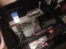
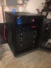
From this angle you can see the front of the shut off switch also. When I moved the battery bank into the cabinet, I did also move a few things around. I pushed the buss bars and BMS panels back a bit, and the panel in front has 12 and 24 volt DC-DC converters with breakers. And 2 more breakers for a direct battery 48 volt connection as well as a feed for a smaller inverter. I am thinking of a 1,000 watt sine wave inverter for some power from the battery as I can just roll this chassis away and use it is a "portable" 18 Kwh power bank. I have XT-60 connectors for the DC outputs. and I can also plug in my 600 watt battery charger to the 48 volt battery direct connection.
IMG_8566.JPGHere you can see the extra blue heat sink on the front side of the panel where the BMS is located. Since this, I also added bars across the front of the 3 battery modules. The 1/8 inch thick aluminum plates are not quite strong enough and the plates were starting to bow outwards about 3/16 of an inch. The factory end plate on the back side is steel.
 
I am planning to fuse my batteries similar to yours. I have the same MRBF holder as you and I ordered a 225A class T fuse and holder.
My MRBF fuse distribution busbar will be for the batteries and the class T fuse will be near my charge controller.

That's the current plan anyway. Thanks
 
Hi guys, just stumbled on this thread while I was deciding what BMS to use. Setting up 8 Lishen cells for a 24V 272A system. That will be connected to a 24V Multiplus 3000/70. I need to figure out what BMS can handle the load, and What would the real load be? I can't find info on what the draw is on the Victron. I only know they suggest a 300A fuse and 50mm cable.

Does anyone know the amp draw by the Victron? Is there a Heltec that would be a good combo for my 8s and amp draw? I read about the active cell balancing and that would also be of interested.

Thanks!
 
The Multiplus can handle a continuous draw of 2500W, so using that as the maximum load you're going to pull, you end up with a current draw at battery side of 105A for your 24V system. With some losses and margins included, I would say you want to spec that at 125A minimum. To play it safe, you would need to get the 200A version of the BMS since you probably don't want to run these near their max all the time (even though I had good results, it's still a good idea to play it safe).
 
The Multiplus can handle a continuous draw of 2500W, so using that as the maximum load you're going to pull, you end up with a current draw at battery side of 105A for your 24V system. With some losses and margins included, I would say you want to spec that at 125A minimum. To play it safe, you would need to get the 200A version of the BMS since you probably don't want to run these near their max all the time (even though I had good results, it's still a good idea to play it safe).
Thanks so much! I had figured out or was told that the draw was over what the Overkill one could do so I was evaluating Daly, and since yesterday, the Heltec which if I heard about, I had forgotten. With the news about the Chargery, perhaps it is back in the discussion too. So it seems all three can handle my BMS needs. Do all three do individual cell monitoring? I know some only have maybe 4 batter connections so they aren't monitoring all 8 cells. Are any of the three available domestically, and are supported domestically? I don't mind paying someone in the US more for the product to have local availability and local support if needed.

Since the batteries have arrived, I am anxious to get a BMS. I am pretty set on the Multiplus as it seems to do all I want. I haven't bought solar panels or a charge controller yet as I intend to work on that later, but I would like to get the batteries, BMS, and charger into my TT. I bought the TT used and was told the two batteries on the hitch were good, but they die overnight and resist charging. Probably totally sulfated. So at least for now, I would like to switch from the hitch batteries to the Lishens and hook up the BMS and charger (Multiplus).

Thanks again to everyone who has been such a big help
 
Do all three do individual cell monitoring? I know some only have maybe 4 batter connections so they aren't monitoring all 8 cells. Are any of the three available domestically, and are supported domestically?

All three should monitor individual cells. The reason some don't monitor all is because the user decides to put 2 cells in parallel per monitoring cable, so essentially turning two smaller cells into one cell. I'm not a fan of such a set-up. If you have a 16s bms, it will have 16 monitoring leads, one per cell.

No idea on the availability in your country, but I doubt it.
 
Back
Top