diy solar

diy solar

Heltec BMS' (up to 350A) with Active Balancing & Independent Active Balancers

All three should monitor individual cells. The reason some don't monitor all is because the user decides to put 2 cells in parallel per monitoring cable, so essentially turning two smaller cells into one cell. I'm not a fan of such a set-up. If you have a 16s bms, it will have 16 monitoring leads, one per cell.

No idea on the availability in your country, but I doubt it.
On another thread, the discussion seems to be primarily the Daly but I have yet to find the correct URL as what seemed like the correct URL says in the title it is for 3.2V batteries and the description says it is for 3.7v batteries and NOT for 3.2V batteries. I have asked on the other thread and have asked Daly for a correction.

In the meantime, I haven't been able to find the Heltec version either. After a lot of research on Alibaba I found a version, but doesn't have the active balancing. It seems the Heltec is the only popular BMS with that feature, although according to most, active balancing isn't necessary for a set of new, balanced batteries.

Thanks
 
Deligreen is a good reseller of Daly. Maybe their links are better.
They're pretty good to communicate with.

The Heltec store on Alibaba is where I bought my BMS w/active ballance. Their links are bad too though. You have to communicate with Michelle.
 
although according to most, active balancing isn't necessary for a set of new, balanced batteries.
New Matched & Batched cells, no issue.
New Bulk Commodity even top balanced "maybe" because they will deviate below 3.00V and above 3.400. That can be as much as 1mv per AH of capacity. More deviation = need more "oomph" to balance, passive isn't up to it (too slow for large capacity cells)
New Bulk NOT Top Balanced - cells will go everywhere and go out of balance quickly.

Active Balancing transfer power from Hi cells to Lo Cells.
Passive only burns off Hi Volts but at low amp rate and makes heat as they burn off the power. Only practical IF cells are Matched and even.

I use Passive & Active balancing systems. I am running Used EV Grade 175AH LFP and New EVE 280AH Bulk cells. Active Balancers on all packs, BMS' have Passive Balancing (Chargery BMS, only capable of 1.2A passive) and after a couple of months of serious testing, abuse simulations with Thrash & Full Cycle Runs for Full to Empty and back, I found a "sweet" spot which keeps the cells around 15mv difference.
The final 280 Pack will be added, using Factory Matched EVE's which will also undergo a series of "hard tests" prior to being put into the production bank.

Heltec & QNBBM are two Known Good makers of Active Balancer products. Heltec offers a few variants to accommodate a broader set of needs including higher end 5A+ capabilities (not cheap by any means). More BMS' are appearing with Active Balancing from various companies BUT they are unknown (no history).
 
Also search for JK or Ji Kong BMS as it is the same board as the Heltec. Mine is Ji Kong branded, and I downloaded the Blue Tooth app from the apple store by just searching JK BMS. Mine has now been up and running for 206 days with no issues at all. I have not loaded it past 80 amps on the 20 amp rated, and most days it runs at about 30 amps charge and discharge.
 
What's about phone app, how good it is?
Ali feedbacks say it has bugs and many parameters can't be changed.
 
fafrd,
could you please say what exactly got burnt on your defective BMS?
Maybe make some pictures.
What mosfets are used, etc.?
Sorry, if you'd already answered this.
 
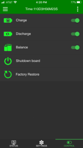
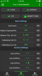
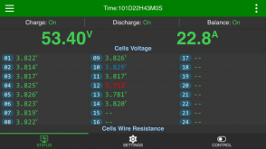
The phone app works great. I have had no issues at all with my Ji Kong BMS. The only odd issue is the first time power up. You need to supply a charging voltage that is more than 5 volts higher than the current battery pack voltage. This was a problem for me as my battery was near full charge so the charger output was only 3 volts higher so it didn't turn on from that. Once it powers up, then all is good. Once it powers up, then the Bluetooth will connect and you have to go in and set all the battery bank settings. Then power cycle it again and it does a quick self test and calibrates the balance wire resistances. Then you go to the control page to turn on the outputs and balancing function.
Here are a few screen shots from mine.
IMG_8594.PNGIMG_8593.PNGIMG_8575.PNG
every setting seems to work just fine.
 
The only odd issue is the first time power up. You need to supply a charging voltage that is more than 5 volts higher than the current battery pack voltage. This was a problem for me as my battery was near full charge so the charger output was only 3 volts higher so it didn't turn on from that. Once it powers up, then all is good.

I made a small boost circuit to generate that from the battery and it applies it for a second or so over the BMS. It uses the same switch as the one used to pre-charge the capacitors in the inverter. That way, the BMS kicks in and then the inverter can be started in case something went wrong without having to rely on the MPPT controller.
 
fafrd,
could you please say what exactly got burnt on your defective BMS?
Maybe make some pictures.
What mosfets are used, etc.?
Sorry, if you'd already answered this.
I did already answer somewhere or other, but here is is again;

Not exactly certain what smoked/burned but highly suspect is was one or more of the power transistors, likely the outermost one (nearest non sense-connector end).

The main P- metal busbar-contact that I chose to bolt my P- wire to proved to be defective - it was unsoldered over most of it’s length and only soldered to the main board at the very ends.

So rather than fanning out to the full array of power transistors over it’s entire length so that they could share the load / current equally, all of the 80A current was steered to the ends of the bus / contact bar before going into the main board close to the location of the first and last power transistors.

This is the theory, anyway (that one or more power transistors overheated because they were shutting more than their share of the 80A being discharged) but the actual reason isn’t all that important because of the obvious manufacturing defect (unsoldered bus bar / contact).

The main lesson for me is to carefully inspect any of these cheapo Chinese electronics before putting in service for power applications.

The second lesson for me is that these all—in-one BMSs may be fine for lower current levels, but for high sustained current levels of 100A or more, the Chargery architecture with external contactor is starting to strike me as a far superior architecture (separate the ‘brains’ from the disconnect where all the heat is generated and active cooling can be used...).

And to be fair, I’m a bit surprised, but it seems I have stress-tested my BMS far more severely than most on this Forum.

I ran 80A continuously for 1 hour before I saw the plume of smoke and halted the test. My actual goal for the test was to fully discharge at 80A for a full 3-1/2 hours.
 
And to be fair, I’m a bit surprised, but it seems I have stress-tested my BMS far more severely than most on this Forum.

I have a 100A version I tested to 100A for quite some time (it's been 6 months or more, can't remember, but several hours). I regularly put in 40A as well to charge (8 hours straight) without issue.
 
I have a 100A version I tested to 100A for quite some time (it's been 6 months or more, can't remember, but several hours). I regularly put in 40A as well to charge (8 hours straight) without issue.
Cool.

Yeah, my charge current is only 30A today but planned for 80-100A in the future and my discharge will be limited to 80A most of the time but can spike to as high as 240A during a power outage (in the case I decide we want to use the 3000W electric oven to bake a pie during a).

So I want to be certain my 300A BMS can handle 80A no problem for a full 3-1/2 hour charge or discharge cycle and can surge to at least twice that for 15 minutes at a time without giving up the ghost.

The fact your 100A Heltec had no problems with a 100A stress test is reassuring - are you relying on passive cooling only or do you have a heatsink or fan on it?
 
fafrd,

thanks for reply.
Unfortunately without knowing the root cause of your incident it's really hard to tell whether it was soldering issue of your particular board or it is design flaw itself. Maybe they are using cheap mosfets with high Rdson and overheating over long period of time is naturally expected and better heat sink is needed.

GXMnow, upnorthandpersonal,
thanks for info!
 
The main P- metal busbar-contact that I chose to bolt my P- wire to proved to be defective - it was unsoldered over most of it’s length and only soldered to the main board at the very ends.
As I recall you had another BMS to compare with right? And the other BMS was soldered correctly?
 
Unfortunately without knowing the root cause of your incident it's really hard to tell whether it was soldering issue of your particular board or it is design flaw itself. Maybe they are using cheap mosfets with high Rdson and overheating over long period of time is naturally expected and better heat sink is needed.

Should you ever end up just having it sit there after a refund or something, let me know. I'd like to have a look and do a post-mortem (if you're not) and see if I can fix it or even play with a different set of mosfets.
I'll pay for shipping it over...
 
fafrd,

thanks for reply.
Unfortunately without knowing the root cause of your incident it's really hard to tell whether it was soldering issue of your particular board or it is design flaw itself. Maybe they are using cheap mosfets with high Rdson and overheating over long period of time is naturally expected and better heat sink is needed.

GXMnow, upnorthandpersonal,
thanks for info!

Given the Vdrop across the BMS it was definitely a manufacturing flaw (and the bad soldering is a dead give away too) ;)
 
fafrd,

thanks for reply.
Unfortunately without knowing the root cause of your incident it's really hard to tell whether it was soldering issue of your particular board or it is design flaw itself. Maybe they are using cheap mosfets with high Rdson and overheating over long period of time is naturally expected and better heat sink is needed.

GXMnow, upnorthandpersonal,
thanks for info!
You are over complicating it. It’s a manufacturing flaw, plain and simple. I have a second unit without that flaw and I’ll report the results once I get around to testing it...
 
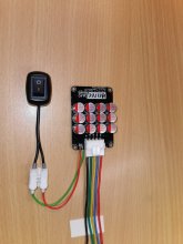
Anybody know if this active balancer can be enabled/disabled via a switch?
I want to leave it connected along with my bms and only turn it for scheduled maintenance as required.
UPDATE: provide link for clarity
In case you didn't find out yet: there is a solder bridge on the board named "run". If you remove the solder und connect the tiny pads to a switch, you can enable or disable the Balancer.2021-02-01 16.55.13.jpg
 
In case you didn't find out yet: there is a solder bridge on the board named "run". If you remove the solder und connect the tiny pads to a switch, you can enable or disable the Balancer.View attachment 35730
nice tip!!!!!

i was considering using bistable/latching relay for each balance cable.

using the run switch is a much more elegant solution

thank you, Hans
 
Back
Top