Thank you for clarifying my statement. Yes, obviously they can be hooded up this way, but you lose the ability to monitor and balance each individual cell in both banks. Kinda defeats the purpose...It is possible to connect sets of 2 or more cells in parallel then connect the sets in series. It is better not to do it that way because you can't monitor each cell unless you connect them separately to the BMS.
You are using an out of date browser. It may not display this or other websites correctly.
You should upgrade or use an alternative browser.
You should upgrade or use an alternative browser.
Heltec (JK) 200A Smart BMS with 2A Active Balance
- Thread starter ArthurEld
- Start date
GXMnow
Solar Wizard
- Joined
- Jul 17, 2020
- Messages
- 2,702
My first two strings are sharing one JK-BMS.
My original plan was to hard parallel the two sets of cells at each cell group. But that was just not practical. So the solution I came up with is a bit odd. The negative ends of the two strings go to a buss bar and into the BMS. The positive ends have separate 100 amps fuses before the disconnect switch, and then out through a class T fuse to the output. Then the 15 balance leads each have two 3 amps fuses. One fuse goes to the cell test point of each bank. The resistance between the two banks is quite low and is holding the cell group from one string in balance with the opposite string. And then the BMS can balance between cell groups. If anything goes wrong, and the two strings are off balance at any point, the balance lead fuses will pop quite easy. And that will cause a cell voltage error so the BMS will shut down. 30 fuses was a pain to wire up, but it all works nicely. The wiring is all easily able to handle the normal operating balance current. With the battery bank at rest, I have pulled out a few fuses and measured the cells, and they are holding perfectly balanced between the two banks.
When I built up the second pair of batteries, I did not want to deal with all the extra wiring and fuses. So I went with 2 dumb BMS units which ended up costing less than the one JK-BMS. And if one fails, I only lose half the battery bank. On my old bank, the one BMS is a single point failure which shut it all down from a bad plug on the BMS. On the new bank, it is two completely separate systems. They only join after the fuses and disconnect switches. Having done both, I like having separate BMS units per string.
fshan
New Member
- Joined
- Mar 30, 2022
- Messages
- 26
New here so forgive me. I am buying 64 cells to start my system. Question: So your second system with 2 dumb units, If one shuts down it will remove the charge current from that string correct? If so I like that. I will have 4 strings and using one bms and 1 balance lead for 4 cells in parallel just bothers me. I know they are forced to be the same voltage but whatever bad thing that would happen to one cell will affect the other 3.My first two strings are sharing one JK-BMS.
My original plan was to hard parallel the two sets of cells at each cell group. But that was just not practical. So the solution I came up with is a bit odd. The negative ends of the two strings go to a buss bar and into the BMS. The positive ends have separate 100 amps fuses before the disconnect switch, and then out through a class T fuse to the output. Then the 15 balance leads each have two 3 amps fuses. One fuse goes to the cell test point of each bank. The resistance between the two banks is quite low and is holding the cell group from one string in balance with the opposite string. And then the BMS can balance between cell groups. If anything goes wrong, and the two strings are off balance at any point, the balance lead fuses will pop quite easy. And that will cause a cell voltage error so the BMS will shut down. 30 fuses was a pain to wire up, but it all works nicely. The wiring is all easily able to handle the normal operating balance current. With the battery bank at rest, I have pulled out a few fuses and measured the cells, and they are holding perfectly balanced between the two banks.
When I built up the second pair of batteries, I did not want to deal with all the extra wiring and fuses. So I went with 2 dumb BMS units which ended up costing less than the one JK-BMS. And if one fails, I only lose half the battery bank. On my old bank, the one BMS is a single point failure which shut it all down from a bad plug on the BMS. On the new bank, it is two completely separate systems. They only join after the fuses and disconnect switches. Having done both, I like having separate BMS units per string.
GXMnow
Solar Wizard
- Joined
- Jul 17, 2020
- Messages
- 2,702
Correct. With the two separate BMS units, each string is separately managed. So if one cell goes over volt, it will stop that string from charging. If any cell goes under volt, then that string will shut off load current.New here so forgive me. I am buying 64 cells to start my system. Question: So your second system with 2 dumb units, If one shuts down it will remove the charge current from that string correct? If so I like that. I will have 4 strings and using one bms and 1 balance lead for 4 cells in parallel just bothers me. I know they are forced to be the same voltage but whatever bad thing that would happen to one cell will affect the other 3.
The only bad thing that I am thinking about is if one of the BMS units self resets after a problem. Let's say during charging, a cell goes over volt. The rest of that string was close to full charged, but then it becomes disconnected. Ideally, the BMS will still allow load current to pull from the string, so the cells will come down a bit and it should reconnect fairly soon so the two strings will be fairly close in charge level. But if it allows one string to discharge a bit, and then the BMS reconnects the strings while they are at a different state of charge, then a very high current could flow between the two strings of cells. That is why I went with fast blow 100 amp fuses on the battery strings. Those should pop before it can damage anything.
I have a total of 3 BMS units all going to the same inverter charge now. When I went to add the 2 new strings to the original single BMS 2 string system, it took me 2 days to get all 4 strings of cells to the exact same voltage before I close the disconnect switches.
Many packs use multiple cells in parallel on a single BMS. Tesla batteries are about 70 cells in parallel in each group. They do have an intentional weak spot where the bus bar sheet is spot welded to each cell to act as a fuse so if a cell does short internally, it should disconnect from the others. My Chevy Bolt packs use much larger cells, but it still uses 3 cells in parallel in each cell group. They have the 3 tabs all directly spot welded together. If a cell shorts, it will drag the other 2 cells down. But to be honest, an internal cell short is very rare on cells that are not being stressed. Most of the time there is a cell under or over volt event, it is due to a charging or discharging error. And having the BMS monitor a group of cell in parallel is still going to disconnect when a cell group reaches the voltage limits. The cells will still be in parallel, but they are all too high or too low and they all need to recover the same as a group.
hwse
Solar Enthusiast
- Joined
- Jan 2, 2021
- Messages
- 585
Have you watched any of Andy's (Off Grid Garage) videos on banks with different SOC connected in parallel? He was surprised by how "non-eventful" it was. I think that given the low voltage difference and the resistance in the interconnecting wires, the current is mild enough to not be a problem....
The only bad thing that I am thinking about is if one of the BMS units self resets after a problem. Let's say during charging, a cell goes over volt. The rest of that string was close to full charged, but then it becomes disconnected. Ideally, the BMS will still allow load current to pull from the string, so the cells will come down a bit and it should reconnect fairly soon so the two strings will be fairly close in charge level. But if it allows one string to discharge a bit, and then the BMS reconnects the strings while they are at a different state of charge, then a very high current could flow between the two strings of cells. That is why I went with fast blow 100 amp fuses on the battery strings. Those should pop before it can damage anything.
...
I'll be glad when they fix the software, My 1st 3 units work ok,, the volt and amp meter are fairly steady, but i never can get the columb meter right, it's better, 1 string is about 75Ah, but i had to set the Bms capacity to 200ah to get things to read near correctly... the 3 other units i got not too long ago,, the amp meter is jumping around like crazy.. I inquired about them, they told me the software had some changes, But it made things worse.. so for right now, as long as they are charging and working ok, i don't pay too much to them. but it would be nice to update all 6 of them to something that monitors / displays proper info on the app.Not yet. I know how to flash it, I can write a bootloader for it so one can update over Bluetooth/UART - I'm just waiting for them to release the source code which they said they would.
I have a BMS for each string of batteries. then all is paralleled to a bus bar.Hey mate, I've ordered another 16 eve 280ah cells and want to connect into my existing set up. Do I buy another Jkbms to monitor second bank or connect using 1 x BMS and batteries in parallel somehow?
Any help appreciated bro
copec
Solar Enthusiast
- Joined
- Jan 23, 2021
- Messages
- 335
Does anyone know where I can get some extra BMS plug/pigtails? What the spec name of the plug is? 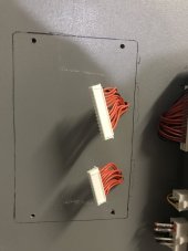
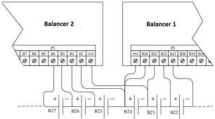
I wish that the BMS that uses a shunt and contactor could be too, then it would be an extremely economical medium/high voltage BMS!

I fail English, but I'm addressing the BMS by the fact that it uses a shunt, not that it is supplied with it. The JK balancers can be stacked like this:As I say these are not yet deployed and that deployment may still be a while yet.
- The batteries have still to be purchased.
But all 4 BMSs came with an external shunt supplied. (500A/75mV ---(I think, without unboxing them again to be definite)).

I wish that the BMS that uses a shunt and contactor could be too, then it would be an extremely economical medium/high voltage BMS!
You can find those cables on Aliexpress and the like, look for balance cables or battery protect cables. In any case, it's a JST-XH connector, 2.5mm pitch.
Edit, e.g.: https://www.aliexpress.com/item/1005002915311598.html
Edit, e.g.: https://www.aliexpress.com/item/1005002915311598.html
Sanwizard
Solar Wizard
- Joined
- Feb 2, 2021
- Messages
- 2,714
Nope. I do it the old fashion way with a 9V battery on top of my 48V system.View attachment 96170
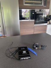
Got my JK BMS recently. It had some extra gear which as I understand it should be able to start the BMS without a battery. Not sure if it’s worth using, have anyone tested it? Seen any YTers try it?
It had some extra gear which as I understand it should be able to start the BMS without a battery. Not sure if it’s worth using, have anyone tested it? Seen any YTers try it?
I've torn it apart to see what's in it: it uses too much power even when the display is off in my opinion. You can replace it with just a button. More here:

Hankzor JK BMS with screen and power button
Any idea if the "turn BMS ON"-button connects two pins somewhere? As soon as I have it I'll open it up and compare with an older one.
and

Hankzor JK BMS with screen and power button
You don't need to set an address: both BMS will show up as a different com port/tty. I guess, if you connect it to Rpi but if you connect it to another rs485 port (on an inverter for example) each bms would need to advertise an address as per attached protocol description. Does attached...
If you do not want the parasitic drain, can you just unplug the display after it is started?
Yes.
Finally got mine installed. I somewhat panicked when I plugged BMS connectors in and nothing happened.. at least there was no magic smoke.. Then remembered I have to hold the button down on display for few seconds and then it came alive. ? Most annoying thing of the BMS is still the short 7AWG cables.
Don't have the battery connected to the system yet so positive cable not connected and disconnect switch not going anywhere.. and yes I'll trim the cable ties.
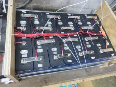
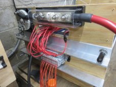
Don't have the battery connected to the system yet so positive cable not connected and disconnect switch not going anywhere.. and yes I'll trim the cable ties.


Looks good. Are you using just one of the supplied 7-AWG cables to the Batt - terminal, or did you join 2 supplied cables to a new and larger cable, for attachment to the battery lug?Finally got mine installed. I somewhat panicked when I plugged BMS connectors in and nothing happened.. at least there was no magic smoke.. Then remembered I have to hold the button down on display for few seconds and then it came alive. ? Most annoying thing of the BMS is still the short 7AWG cables.
Don't have the battery connected to the system yet so positive cable not connected and disconnect switch not going anywhere.. and yes I'll trim the cable ties.
View attachment 96399View attachment 96400
For my small 4s battery pack (using the new model 8S-200A with the 'heater port' present), I'll probably be using the 2 provided cables direct to the battery's "-" terminal. However, I will probably need to combine the "P-" pair to a single larger cable, in order to connect my coulomb-counter shunt more easily, and also creating a bit more free length to work with.
I was provided with both the small monitor display AND a simple activate/deactivate switch, which fits the same port. I assume that the 'simple switch' consumes less power, but I will be verifying functionality of with both devices before I put the battery into production.
Last edited:
That's only his top-most BMS lead, he hasn't connected the main "Bat +" supply cable yet.Looks very nice and organized.
In the first photo, your main positive lead out from the battery looks a little light to my eye. What is that 18-guage?

Yes. currently "hacked" both together using two 6AWG crimp on connections to a short 4AWG..Looks good. Are you using just one of the supplied 7-AWG cables to the Batt - terminal, or did you join 2 supplied cables to a new and larger cable, for attachment to the battery lug?
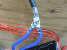
I only had the display with switch. I ordered the BMS on April 20th.I was provided with both the small monitor display AND a simple activate/deactivate switch, which fits the same port. I assume that the 'simple switch' consumes less power, but I will be verifying functionality of with both devices before I put the battery into production.
Similar threads
- Replies
- 2
- Views
- 268
- Replies
- 0
- Views
- 127
- Replies
- 40
- Views
- 3K


