The only thing going for the Seplos BMS is communication, but Andy is unsure how good that is. This is version one and will improve in the future, maybe they also come out with a better balancing solution on the BMS. The inability to shut down the battery is a concern. It does look very neat, better than many prebuilt rack batteries. For a beginner it looks almost fool proof to build. I liked the inbuilt 400A fuse, but wonder about its quality. T-fuses are not cheap. I had a quote from Luyuan for their case delivered DDP to UK, about $370 with everything h you need except BMS. A 200A JK BMS was recommended at $133. Total $500, $120 less than Seplos. Positives about the Luyuan case are external breaker and JK BMS. Negatives more chance for a beginner to confuse themselves connecting balance leads or BMS, no communication. The compression looks better in the Seplos, but Andy may be right about the rubber and cooling. I am now leaning towards the Luyuan case with a JK BMS.


You are using an out of date browser. It may not display this or other websites correctly.
You should upgrade or use an alternative browser.
You should upgrade or use an alternative browser.
Heltec (JK) 200A Smart BMS with 2A Active Balance
- Thread starter ArthurEld
- Start date
phaberest
New Member
- Joined
- Dec 4, 2020
- Messages
- 15
Hi guys!
I assembled a 8S 24V 280Ah with the Heltec 200A 2A bms but I'm experiencing weird issues with the charging or, to better say, it barely charges. I'm not getting any error out of it and it doesn't look like it is turning off the charge, but in an entire night with the inverter-charger connected to the grid and the day after with solar it just added 10%.
It is supposed to charge the entire pack in about 5 hours considering that the inverter can push 50A
What could it be?
ArthurEld
Solar Wizard
It could be bad connections.
phaberest
New Member
- Joined
- Dec 4, 2020
- Messages
- 15
But it discharges without any problem, I mean the load works just fine ?It could be bad connections.
I double checked the leads and they all report the voltage of the cells correctly
labeeman
Solar Enthusiast
Could be your load is really close to what your charger is capable of.
Sanwizard
Solar Wizard
- Joined
- Feb 2, 2021
- Messages
- 2,714
Is it pushing 50amps? Did you test with a DVM? What is the state of charge of the batteries? Did you top balance? If the amperage is low, it may take a while. What did you set as your bulk charge and float voltages?Hi guys!
I assembled a 8S 24V 280Ah with the Heltec 200A 2A bms but I'm experiencing weird issues with the charging or, to better say, it barely charges. I'm not getting any error out of it and it doesn't look like it is turning off the charge, but in an entire night with the inverter-charger connected to the grid and the day after with solar it just added 10%.
It is supposed to charge the entire pack in about 5 hours considering that the inverter can push 50A
What could it be?
labeeman
Solar Enthusiast
To add to that did you set your BMS for the type battery mine came set for the wrong one.
phaberest
New Member
- Joined
- Dec 4, 2020
- Messages
- 15
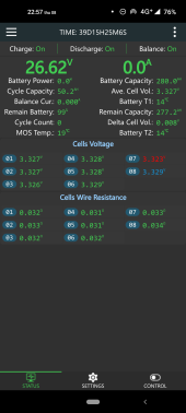
This is another weird thing: the charger shouldn't be able to provide more than 50A, but as you can see in the screen record I did on the app during the charge from grid it fluctuated like crazy showing even ~90A of charge.Is it pushing 50amps?
The inverter/charger is a RP 3024E and I both tried setting it with the B-L value in param 05 (battery type) as well as setting B-0 (user defined) and setting the charge voltage to 28.6. The results were the same.
Sadly I don't have oneDid you test with a DVM?
It started at about 30% since they were left resting about two months waiting for being installed in my RV. I had first top balanced them with my 5A power supply and assembled them after they reached 0.250A at 3.60VWhat is the state of charge of the batteries? Did you top balance?
28.6 bulk and 27.4 floatWhat did you set as your bulk charge and float voltages?
Attachments
phaberest
New Member
- Joined
- Dec 4, 2020
- Messages
- 15
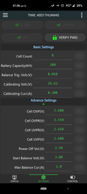
Yep, I used the password 123456 to get in the edit mode and set it to be Lifepo4 (the top right of the buttons) and adapted the continuous charge to 150A since it was lower by default (will probably never reach that current, but I raised it anyway while testing workarounds)To add to that did you set your BMS for the type battery mine came set for the wrong one.
labeeman
Solar Enthusiast
If you are going to do DIY solar stuff you need to correct this.Sadly I don't have one
phaberest
New Member
- Joined
- Dec 4, 2020
- Messages
- 15
I have a multimeter that can show me the volts up to 3 decimal places, but I cannot measure the amperage if it's over 10AIf you are going to do DIY solar stuff you need to correct this.
I guess I didn't get the question correctly at first ? tired and stressed, sorry guys
labeeman
Solar Enthusiast
These work well and can show amps AC and DC by just clamping the wire. and will not break the bank.I have a multimeter that can show me the volts up to 3 decimal places, but I cannot measure the amperage if it's over 10A
I guess I didn't get the question correctly at first ? tired and stressed, sorry guys

GXMnow
Solar Wizard
- Joined
- Jul 17, 2020
- Messages
- 2,702
Watching the video, it looks to me like a bad connection somewhere. The charger is trying to hit the rated current, but then the voltage goes too high so it has to cut back, then the voltage drops so the current ramps up again. The BMS voltage is not spiking up much, so the bad connection could be outside of the battery pack. I did see some voltage spiking on the cell voltages, but it is hard to see if there is any one going bad. The individual cell voltages are only scanned by the JK BMS. So they do not update as fast as the current reading. Check every connection while not under load. Then try just a small charge current, like say 3 amps and se if the jumping stops. The one small problem with the JK BMS is that it samples the current and reads the immediate reading, no averaging. And AC mains chargers tend to have 100 or 120 Hz ripple current. So the reading will bounce up and down a bit as it takes a current reading at different parts of the sine wave current ripple. I see that on my system when the XW-Pro inverter is charging the battery.
The spikes over 50 amps are likely due to the bad connection. The charger is raising the voltage to try to keep the set current and then the bad connection is making contact again and the current jumps before it can respond and catch it. Even just the caps in the charger hitting into the batteries can make a big current spike if they charged up 2 or 3 volts and then connected. What material are your bus bars on the cells? What connections are between the charger and the battery system? Many LFP cells are aluminum studs, so you need to sand then lightly and use something like NoAlOx to ensure a good electrical connection.
The spikes over 50 amps are likely due to the bad connection. The charger is raising the voltage to try to keep the set current and then the bad connection is making contact again and the current jumps before it can respond and catch it. Even just the caps in the charger hitting into the batteries can make a big current spike if they charged up 2 or 3 volts and then connected. What material are your bus bars on the cells? What connections are between the charger and the battery system? Many LFP cells are aluminum studs, so you need to sand then lightly and use something like NoAlOx to ensure a good electrical connection.
phaberest
New Member
- Joined
- Dec 4, 2020
- Messages
- 15
The bus bars are "heavy duty" rated for up to 300A, but I will check them (in fact I checked only the posts on the batteries, not sure about the bus bars). i bought them off Amazon https://www.amazon.it/dp/B09MRWBM8WWatching the video, it looks to me like a bad connection somewhere. The charger is trying to hit the rated current, but then the voltage goes too high so it has to cut back, then the voltage drops so the current ramps up again. The BMS voltage is not spiking up much, so the bad connection could be outside of the battery pack. I did see some voltage spiking on the cell voltages, but it is hard to see if there is any one going bad. The individual cell voltages are only scanned by the JK BMS. So they do not update as fast as the current reading. Check every connection while not under load. Then try just a small charge current, like say 3 amps and se if the jumping stops. The one small problem with the JK BMS is that it samples the current and reads the immediate reading, no averaging. And AC mains chargers tend to have 100 or 120 Hz ripple current. So the reading will bounce up and down a bit as it takes a current reading at different parts of the sine wave current ripple. I see that on my system when the XW-Pro inverter is charging the battery.
The spikes over 50 amps are likely due to the bad connection. The charger is raising the voltage to try to keep the set current and then the bad connection is making contact again and the current jumps before it can respond and catch it. Even just the caps in the charger hitting into the batteries can make a big current spike if they charged up 2 or 3 volts and then connected. What material are your bus bars on the cells? What connections are between the charger and the battery system? Many LFP cells are aluminum studs, so you need to sand then lightly and use something like NoAlOx to ensure a good electrical connection.
Yesterday I tried again and it's getting even weirder, now the BMS is stopping the charge for cell over voltage and shows the battery as charged but the cells are all around 3.32
Attachments
phaberest
New Member
- Joined
- Dec 4, 2020
- Messages
- 15
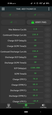
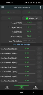
Here they areCan you post a screen shot with all of your parameters?
Attachments
GXMnow
Solar Wizard
- Joined
- Jul 17, 2020
- Messages
- 2,702
Since you are getting a cell over voltage error now, I am pretty sure you have a bad connection between a pair of cells. It does not take much at all. A little intermittent resistance will cause the voltage to rise up under charge current which trips the high voltage cut. Even if it is tight, a small amount of aluminum corrosion on the cell terminal can cause it to happen.
phaberest
New Member
- Joined
- Dec 4, 2020
- Messages
- 15
All right, let's try to softly sand the terminals and redo all the connectionsSince you are getting a cell over voltage error now, I am pretty sure you have a bad connection between a pair of cells. It does not take much at all. A little intermittent resistance will cause the voltage to rise up under charge current which trips the high voltage cut. Even if it is tight, a small amount of aluminum corrosion on the cell terminal can cause it to happen.
Thank you guys, btw, I was completely in the dark before asking to you here
Last edited:
ArthurEld
Solar Wizard
Dude, check the resistance. Watch this video. He starts checking the resistance at about 4:00
Here's another good one-
Here's another good one-
Last edited:
Similar threads
- Replies
- 2
- Views
- 268
- Replies
- 0
- Views
- 127
- Replies
- 40
- Views
- 3K