diy solar

diy solar

Heltec (JK) 200A Smart BMS with 2A Active Balance

LOL this happened to my 12V when i tried to jumpstart my BMS... big bright spark, life flashed before my eyes and I thought i had died hahaha (is it just me or does the thought of working with LFP banks that can dump >30kW's of current instantaneously scare the crap outta other people too?)
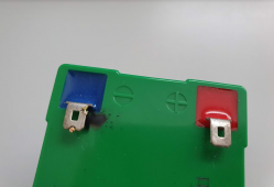
1620271076095.png

this happened tho cos my P- on the BMS was also connected to other banks in parallel, as well as the inverter (ie: what the final setup will look like).. so, SOMETHING in the system (probably inverter tbh) has a giant capacitor in there and it's obviously not 12V, so when this tiny 12V battery got introduced to the BMS, there must've been a huge voltage potential somewhere else that suddenly did this...

That said though, no damage to the BMS (that I can tell), it did start as expected... inverter didn't throw a code, and this battery survived too (it's a small 12V 10Ah with a tiny BMS inside), the battery itself continued to work at 12V, the internal BMS wasn't fried... everything seems to work just fine. I just wasnt expecting a massive zap thats all
 
That is why I put a resistor in series when I used my RC car battery pack that can push current. I also only jump start the BMS when my shut off switch to the inverter is open. You have to think about the possible current paths.
 
LOL this happened to my 12V when i tried to jumpstart my BMS... big bright spark, life flashed before my eyes and I thought i had died hahaha (is it just me or does the thought of working with LFP banks that can dump >30kW's of current instantaneously scare the crap outta other people too?}

I'm kind of ignorant about electricity. Shorts on these batteries seem more like explosions to me.
 
Last edited:
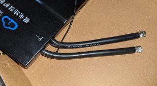
Just received my jk-b2a24s-15p (2A-150A/300A), what's everyone's thoughts on the 2 x 7AWG cables.

-Combine the the two wires into one lug, or keep them separate?
-Are these a little undersized for a 16s/48v MPPSolar 5kW setup?

jk.JPG
 
My JK b2a24s20P 200 amps 350 peak BMS has the same two #7 awg wires for the P- and B- leads. Yes, they do seem a bit light for 200 amps. The only reason they can push them that hard is the 200C insulation temp rating. That silicone insulation can take some crazy heat. I have not pushed mine past 82 amps yet. Running 80 amps for nearly an hour, those wires were warm to the touch, but not hot. On the B- input side, I put on 2 separate lugs and connected them to the 2 center studs of a 4 post buss bar. The two cables from my battery bank go to the two outer studs. This way only about half the current goes through each end of the buss bar. The two wires should evenly share the current, and the middle of the buss bar is basically taking no current at all. On the P- output side, I shortened the wires about 2 inches and used a heavy coper crimp splice to connect those two leads to a 2/0 cable that goes to my output buss bar. I am only measuring 1 milliohm of drop from the input buss bar to the output buss bar. That is dropping just 80 millivolts at 80 amps. That 80 amps was from drawing about 4,000 watts out of my inverter with the battery at about 53 volts. Maximum power to or from my inverter charger is about 140 amps. It looks like it will take that without a problem.
 
My JK b2a24s20P 200 amps 350 peak BMS has the same two #7 awg wires for the P- and B- leads. Yes, they do seem a bit light for 200 amps. The only reason they can push them that hard is the 200C insulation temp rating. That silicone insulation can take some crazy heat. I have not pushed mine past 82 amps yet. Running 80 amps for nearly an hour, those wires were warm to the touch, but not hot. On the B- input side, I put on 2 separate lugs and connected them to the 2 center studs of a 4 post buss bar. The two cables from my battery bank go to the two outer studs. This way only about half the current goes through each end of the buss bar. The two wires should evenly share the current, and the middle of the buss bar is basically taking no current at all. On the P- output side, I shortened the wires about 2 inches and used a heavy coper crimp splice to connect those two leads to a 2/0 cable that goes to my output buss bar. I am only measuring 1 milliohm of drop from the input buss bar to the output buss bar. That is dropping just 80 millivolts at 80 amps. That 80 amps was from drawing about 4,000 watts out of my inverter with the battery at about 53 volts. Maximum power to or from my inverter charger is about 140 amps. It looks like it will take that without a problem.
My inverter puts out 185A but I don't want that much going thru my BMS. I plan to set the BMS max charge and max discharge amps to 100.
And use 125A class T fuses on each battery.
It would be nicer if my system could run on one battery but I don't want to try using 185A with my BMS. It seems much safer to only use 100A for each battery anyway.
 
Didn't get a chance to fiddle with the cables, but as we had 3 over cast days I did get to see the behaviour of the pack in the low end of the cycle.

With this in mind, and having to go through the process again of restarting the BMS, pre-charging caps etc, thoughts on the following.

Cold starting BMS.
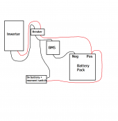
1) Wire a 9v battery between the battery main pos and the output side of the BMS (which is on the neg side) with a moment switch in-line so I can push button restart the BMS (given we need to see a solid 5v+ on the output side of the BMS this should give me 60v+). I don't think the BMS needs to see current on the output side to start, just voltage so there should be no draw across the 9v battery as far as I understand it. Can this be done or is this is a recipe to blow up the 9v?

Pre-charging inverter caps.
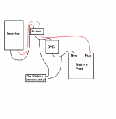
2) Wire a 25w 50 Ohm resistor between the battery main neg and the output side of the BMS with a moment switch inline so I can push button pre-charge the caps in the inverter to stop the BMS seeing the inverter boot as a dead short.

This is the current wiring and so far I have used a 30v DC power supply and a boost convertor with some alligator clips to allow me to reboot the BMs or pre-charge inverter caps as needed, which is a bit fiddly getting it all out.

I could just as easily not wire any of this in and just have it all setup in a jiffy box with the push buttons mounted on it and some alligator clamps hanging out of it to use as needed as there are some logistical issues with terminal sizes etc given these 2 little add on systems wouldn't use heavy gauge wire or large lugs and the output side of the BMS is all heavier gauge stuff.

View attachment 48479
 
My inverter puts out 185A but I don't want that much going thru my BMS. I plan to set the BMS max charge and max discharge amps to 100.
And use 125A class T fuses on each battery.
It would be nicer if my system could run on one battery but I don't want to try using 185A with my BMS. It seems much safer to only use 100A for each battery anyway.
What inverter are you using that puts out 185 amps? Is that DC or AC amps?

I am looking to support a whole house 200 amp service via Inverters, but it looks like that would take 48KW of inverter power at 240V.
 
Cold starting BMS.
1) Wire a 9v battery between the battery main pos and the output side of the BMS (which is on the neg side) with a moment switch in-line so I can push button restart the BMS (given we need to see a solid 5v+ on the output side of the BMS this should give me 60v+). I don't think the BMS needs to see current on the output side to start, just voltage so there should be no draw across the 9v battery as far as I understand it. Can this be done or is this is a recipe to blow up the 9v?

Pre-charging inverter caps.
2) Wire a 25w 50 Ohm resistor between the battery main neg and the output side of the BMS with a moment switch inline so I can push button pre-charge the caps in the inverter to stop the BMS seeing the inverter boot as a dead short.

This is the current wiring and so far I have used a 30v DC power supply and a boost convertor with some alligator clips to allow me to reboot the BMs or pre-charge inverter caps as needed, which is a bit fiddly getting it all out.

I could just as easily not wire any of this in and just have it all setup in a jiffy box with the push buttons mounted on it and some alligator clamps hanging out of it to use as needed as there are some logistical issues with terminal sizes etc given these 2 little add on systems wouldn't use heavy gauge wire or large lugs and the output side of the BMS is all heavier gauge stuff.
1) NO!!! the battery will just go from the B- to the P- of the BMS and add a 100 ohm or so resistor in series to limit the maximum current once the BMS FET's turn on. The voltage from the battery bank plus to the P- will be pulled to 9 volts more than the battery bank voltage.

2)Do you have a shut off switch or circuit breaker that can be manually turned off between the battery bank and the inverter and charge controller? That should be turned off when you start up the BMS. Then once the BMS is up and working and everything looks good, then you connect the pre charge resistor across your shut off switch or breaker. This will charge up the caps before you close the switch to allow full power.
 
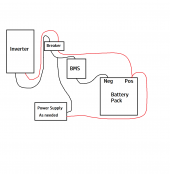
I had an attachment showing how it's wired currently, but I've added some detail showing what I currently do. I think you're missing some of what I'm saying.

See the diagram and then read the below.

1620614946882.png

Whether I am start the BMS or Pre-charging caps to get he inverter going I currently connect a DC PSU to the main batt positive stud and then the lug connection point on the output side of the BMS (-P) between the two wires and the lead in to the breaker (as there's 2 wires from the BMS to the breaker, I simply have lugs on each and a bolt through the centre attaching it to the wire that leads into the breaker, this gives me a surface to clamp to). If I am starting the BMS, I have the breaker flicked off so inverter isn't trying to start and charge its caps, If I'm pre-charging caps after the inverter is booted I have the breaker switched on. while I do it.

I have no sparks or issues with this setup, but it's very fiddly to go get the PSU, boost converter, wire it, put the rubber mat down over the battery for safety, check voltages on the PSU setup with multimeter to make sure everything is spot on etc.

This isn't like the Daly where you can just short P to B, the JK/Heltec needs to see 5v above battery pack voltage on the P side to start. I didn't think it was drawing any current though?

That's why my intention for BMS start was as pictured, with the breaker turned OFF.

1620615884457.png
Similarly, if I just need to pre-charge caps and the BMS is already running, my intention was.

1620616049924.png
 
Where you are showing the BMS start power supply, the supply would need to be about 65 volts. The BMS needs the lead going to the breaker to go more than 5 volts further negative than the pack negative. So where you show the 25W 50ohm resistor, the "battery pack" negative would be the 9 volt battery positive. The side going to the breaker would be the negative side of the 9 volt battery with a 2 watt 100 ohm resistor and momentary switch. Press this button and it supplies the required over 5 volts to power up the BMS. I would do that with the breaker off.

Then put the 25w 50 ohm resistor and momentary switch across the breaker. Are you using a 2 poll breaker? If so, you will need to jump both sides with a 2 pole momentary switch, but one side can be a jumper, and just one side being the resistor. Once the BMS is already on, then you can close this switch to pre charge the caps. Then turn on the breaker.
 
I have a really hard time following what you are saying sorry.

The power supply, with a boost converter, has never needed to be more than about 59v because my pack never goes above 54v.

These are 2 separate issues, with 2 separate setups to solve them. I am not trying to do one thing to solve both issues.

As I showed above, I can solve ALL issues right now by simply connecting my power supply as shown and turning it on. If I'm starting the BMS, I have the breaker switched off (yes it's two pole).
 
I've realised the BMS starting battery setup is wrong, should all be on the neg side.

Also, the resistor setup should all ideally be on the inverter side of the breaker with DPST moment switch across the breaker and a resistor in series with one of the terminals, I'll see what access I can get to the breaker terminals as it has clamp terminals that currently have large gauge and boot laced wires in there already.
 
What inverter are you using that puts out 185 amps? Is that DC or AC amps?

I am looking to support a whole house 200 amp service via Inverters, but it looks like that would take 48KW of inverter power at 240V.
Solark 12K
DC 48V charge or discharge at 185A
I have 4 batteries so less than 50A each.
 
It's not corrupt, I can download and open it just fine. Try it again, different browser maybe.

The LED won't blink until you turn on the BMS with a voltage over the battery voltage.

You will probably have to go over 54.4 for a second. Once it's on, it stays on until you disconnect it.
Is it good when it blinks red? Or should it turn green? It beeped, and is now blinking red. Hope that means all is well
 
Hey DAN, what would I do without you buddy! Thanks! I think you just saved me hours of troubleshooting tomorrow.
Much obliged.
 
Back
Top