diy solar

diy solar

Historical LFP early-adopter misinformation story (long)

Can you provide a source for this statement?

Would you honestly believe a document from a chinese battery manufacturer or a white paper from a grad student over the experience of someone that has been actively involved in these cells for a decade in both stationary and EV applications?
 
Remember too that this is historical remnants from my past. Manufacturing, materials, and processes have likely improved since then.
 
Would you honestly believe a document from a chinese battery manufacturer or a white paper from a grad student over the experience of someone that has been actively involved in these cells for a decade in both stationary and EV applications?
If the document included the omitted information that Substrate spoke of, Yes I would believe it.
 
Remember too that this is historical remnants from my past. Manufacturing, materials, and processes have likely improved since then.
Yes, I appreciate all of your history and I in no way meant to cast any negative vibes toward you.

I have 30 years with FLA cells in off grid use and got a chuckle at: "The FLA guys smiled, but that's the way it is."

In 2012 I was at the annual meeting of a Mega FLA Corp. on Marco Island Florida and could not believe the CEO of a global operation was taking jabs at Lithium technology.

Any way, I own about 70 kWh of LFP and learned more than I knew before asking the question. Thanks:)
 
Ah, no worries. Prior to LFP I did the usual thing starting out: a pair of GC2's, hydrometer, and holes in my shirt and pants. :) Fun.

Progressed to truckbeds full of Optimas or Hawker pure-lead agm's. Keeping those balanced is fun. Doing the fast turnaround cc/cv/cc or IUI protocol, which no consumer charger is capable of doing right.

In fact, I still have a soft spot for agm's - so sad to see them killed prematurely. I just finished off a wall-of-text rant about the Mighty Max hybrid gel's having their cycle use CV being set so high they are prematurely killing the gel. Even Renogy's gel is too high. But a kid starting out might not know the whole story behind that and just blindly accept what's printed on the case - which is WRONG - well unless one enjoys killing 60% of the capacity they paid for in short order...

I love LFP, but lead is just as fun armed with a little knowledge.. :)
 
Solar users may be coming out of a deep knee like this early in the weak morning sun and not know how good that is that it is happening naturally.

Based on tables like for Ganfeng that Dzl posted, I've been telling forum members they should either limit PV/SCC size so C rate matches what the cells can accept at zero degrees C, or determine max C rate possible from their PV/SCC and raise the low temperature limit.


What you've said is that the curve/table ought to also show decreased C rate near 0% SoC.
Is raising low-voltage cutout further up the knee sufficient so max charge rate is fine to start with?

Some BMS communicate what charge current/voltage they want, slow charging so when full any runners stay below max voltage while balancing brings the other cells into line.
Do you know if any BMS also reduce requested charge current for low SoC?


Seems to me for off grid PV, as opposed to "Super Chargers" for impatient EV drivers, we've usually got all day to recharge.
Exception would be if the sun only peeks out for an hour or two before storm clouds take over.
But with excess PV, most days we have some charge current available for 8 hours every day. So batteries can be charged at a constant 0.12C.

(My system is AGM, so it is set for 0.20C, and with DoD limited to 70% possibly 80%, half the day provides bulk charging, other half can do absorption.)
 
Substrate said:
What the simplified lab-charging cycle charts don't tell you is that to achieve that 2000 cycle span, they didn't hit them up at .5 or 1C when down in the discharge knee as they did their cycle test!!
Can you provide a source for this statement? Speaking to the EVE LF280 cells, EVE's charts and instructions do not mention this.
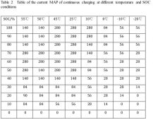
Found the following in a datasheet of the EVE LF280 (file LF280-73103, version B). As far as I understand, it confirms that the cells do not like fast charging at low SOCs, even at normal temperature (25 °C). Regarding their 3500 cycles, those appear to be for 0.5 C charge, 1 C discharge. This appears to contradict their limits for continuous charge?

Hope I'm not misinterpreting things :)

EVE_LF280_charge_rate_map_SOC_temperature.PNG
 
That Eve LF280 table shows 280A charging (1.0C) at 25 degrees C down to 50% SoC
Tapers to 56A (0.2C) at 10% SoC.
Zero A (0.0C) at 0% SoC? How do you ever get out of there? Presumably some very low rate.
But they allow 1.0C all the way to 100% SoC?

Other vendors' tables taper to 0.3C at 95% SoC, 0.0C at 100% SoC.

To be safe I would taper off at both full and empty.
If BMS doesn't offer that function, limit charge current to 0.2C for all SoC. Limit max voltage to about 95% SoC and min to about 20% SoC?

But I'm not sure 20% SoC can be reliably detected by voltage. 20% is what's needed to allow 0.2C at 10 degrees C. If I can only detect 10% SoC, then max charge rate is 0.1C. But BMS should be able to determine SoC directly by counting coulombs, not measuring voltage. However, inverter low (voltage) disconnect is based on volts. Would need BMS telling inverter to knock it off otherwise BMS disconnects.
 
Do you know if any BMS also reduce requested charge current for low SoC?
No, but if they are really interested, perhaps they should. But then how would they divert excess power? Might be too impractical or costly to implement.

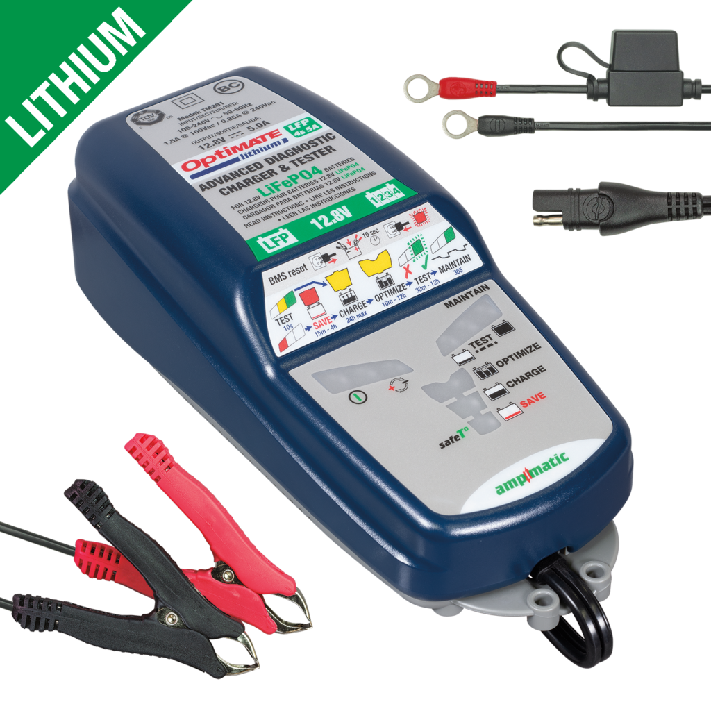
So - now don't laugh - this is not a BMS, but a cross-application example of a charger that if it sees a resting voltage anywhere below 12.8v, it goes into a "save" low current mode. It doesn't last very long, since coming out of the knee is about as fast as dropping into it. And even shorter if you are only half-way into it, and not down at the dregs.

This charger is designed for the very expensive high-rate LFP cells for Motorcycles - typically anywhere from 4ah to say 12ah at the c/20 rate. The point being that even though puny in capacity, it reveals how to get the most life out of an LFP since extremities such as being very very tiny, or in the case of EV motive power, gremlins show themselves, where they might be missed in casual sub-c use.

So these guys knew what the deal is, just like we found out earlier when trying to wake up Winstons rudely for a ride. :)


Thing is, what is practical vs what might be seen as over-engineering is always the question. Didn't get the life you expected out of your bank? Just build a new one.

(My system is AGM, so it is set for 0.20C, and with DoD limited to 70% possibly 80%, half the day provides bulk charging, other half can do absorption.)

The secret to agm's, is that they are prematurely killed by under-charge in a cyclic (daily) routine. There just isn't enough time to charge that last 1% (it can't be rushed) since it takes 10-12 hours of float at 13.6 (no lower!) to complete the charge. This is after absorption!

Knowing this, in a daily cyclic routine with solar, one must perform tricks to limit the inevitable capacity walk-down from not being able to get that last 1% charged. There isn't enough solar insolation time left to do it daily. So the race is on!

Get into CV/absorb as fast as you can. Hold it there for the rest of the day. The sun goes down before you can do any real damage from holding at CV forever.

Or, if your SCC drops into float due to a timer, you do your best and set float for 13.6 to 13.8. Sun goes down before those who consider these elevated float voltages harmful. To be sure, don't go any lower than 13.6v, as that will not complete the charge, it will merely maintain it at 99%, and walkdown slowly occurs.

(Update for lurkers - for this to work properly one is assuming that you aren't starting out with barnyard-finds, second-lifers, or a stack of unbalanced garage-queens to begin with.)

But is it practical, or over-engineered? Instead of doing this, a person might decide to just buy another battery a bit sooner.
 
Last edited:
A somewhat laughable (expensive) story of my early-adopter mis-information woes.

Or read as "What NOT to do!"

Early on, when the only cells we could get in any large capacity to drive DIY EV's and other hobbiest stuff, there seemed to be some confusion about LFP vs Non-LFP charging procedures. We were well aware of the operational differences and the super flat discharge curve of LFP, but still thought that somehow these lithium batteries were in the same family and could use the same charging techniques.

Quite a few of us took our cells to 4.2v, just like non-lfp. We even top-balanced up there. It seemed to work, albeit precariously, but we couldn't pin down why things went downhill so fast. We knew there was no real energy up so high in the knee, but the going theory was the higher you top balance at, so much the better. Even bottom-balancers would do a bank level trigger when the first cell reached 4.2v!

Part of the problem was brought on by early documentation of some ThunderSky prismatics, (1st gen blue ones, not yellow!) that spec'ed out as 4.2v ! Other manufacturers had 3.65, like A123 cylindricals, but you know - these prismatics are more advanced! And nobody was tack-welding A123 cylindricals or pouches on their own - given the problems with counterfeits, used or rejected stock, bad diy tack-welds ... So prebuilt prismatics was the way to go.

Things were going downhill fast after a few cycles. Top balance was hard to maintain, and was always busy. Bottom-balancer guys were doing better, but still..

In the end, after a LONG period of trying to pin down WHY some manufacturers had spec sheets showing 4.2v as the max CV voltage to charge to, it turned out to be a "customer is always right" thing, and not a scientific one. "Sure, you can take these to 4.2v, go ahead - they're your cells!" I don't think it was a case of dishonesty either - I think that many early on, just didn't know for sure.

Anyway, can you say plating from secondary reactions due to high-voltage? We can now, but not then when the cells were NEW and seemed ok for the first handful of cycles out!

This kind of reminded me of the whole gel vs agm CV voltage charging fiasco from many years past! Even today, many don't know the difference.

So when I built my first 4S 12v learner bank, I bought 5 cells. The one with the lowest capacity or highest internal resistance would be the odd man out. I chose the more normal 3.65v as my top-balance CV limit. Whew.

So with that one cell left out, I did a destructive experiment on it in a SAFE ENVIRONMENT:

1) Charged the cell like normal at 3.65v CV, and let it absorb or saturate to full until there was very little tail current flowing.
2) Let it rest for an hour to settle.
3) Changed my CV to 9v to see what would happen in a simulated HVD charging failure.

I put my tracking multimeter on it, and set it to be audible, so at every 0.1v change it would beep.

So with a CV of 9v on this already charged cell, we let loose. Nothing happened. No current flow. No change in voltage.

WOW! Sure looks like they are somehow self-protecting! WRONG. Things were fine for about 15 minutes.

Beep!

Huh, ok. Back to the adult beverage. (not recommended for safety)

10 minutes later:

beep!

Another 10 minutes go by, but now

beep beep

You get the picture. In a very short amount of time:

beep beep beep beep beep beep beep beep.....

Then I disconnected everything and stopped. What was fascinating was that despite ZERO CURRENT flowing to charge, just having a high CV voltage applied caused a change in terminal voltage!!

My best guess here is that the rise in terminal voltage with no current flowing was not a charge reaction, but a secondary chemical reaction (destructive, along with plating) happening. Fascinating.

To circle back to the early days when some were top-balancing at 4.2v, I had to laugh. We were trying to balance at voltages caused by secondary reactions! Egads, no wonder it went so wrong so fast. :)

It was educational to say the least, and worth taking a spare cell to destruction (safely) to learn and watch that happen.
I started in 2008 so understand this well and I too remember the blueish green and orange Thundersky cells. There was no data, no white papers and only incorrect guessed at data sheets. Then there was Jack & EVTV... My first top balance, on Thundersky 60Ah practice cells (waaaaay beofre Yttrium and the Winston Chung / Sinopoly scandal), was to 4.0V. They swelled up. I then backed it down to 3.8V and used cell compression. These days top balancing is done at 3.6-3.65 and charging is done to 3.45VPC to 3.5VPC. Us pioneers learned as we went and did so by destroying quite a few cells in the name of learning.
 
True, It's not easy trying to find early adopters that switched to LFP and have been using in a fractional C use day in and day out. Like you said it would take a long time to get some sort of data other than it works well but not knowing what the true time period that a battery bank can be put in to operation and continuously be used.
My own 400Ah Winston bank is made of cells produced in May of 2009. The bank is used 6 months for marine use then in the off season it is used as the load bank for an alternator testing machine in our shop. It routinely hoovers at between 5% SoC and 20% SoC and is only recharged during the testing of alterntors. If it gets too full we discharge it again. The cells still exceed 400Ah when capacity tested. The cells finally broke 2k cycles about 6 months ago and most cycles have been to 80% DoD or deeper. They have never been floated and only charged to 13.8V / 3.45VPC.. Max routine charge rate for marine use is approx .4C but when used on the test bench we have the capability to throw .6C+ at it.

I have been step-top-balancing since about 2012. Cells are wired in parallel then charged to 3.400V and current is allowed to go to 0.00A. The power supply is then turned up to 3.500V and current allowed to go to 0.00A. The last push is to 3.60V or 3.65V and current is, once again, allowed to go to 0.00A. The step-procedure means the time at high voltage is very short and the cells are not held at a high voltage for very long.
 
@Sabre36 - my man! Truth!

We were so voltage-obsessed that we missed the fact, that given enough time, one could reach 100% SOC at 3.45v

That's the hardest lesson simply because there is no TIME jack on our Fluke multimeters. :)

That too is why I always recommend at least ONE Fluke in the shop - when we were skirting the line between 4.2v top balance, and electrolyte breakdown, your home-improvement store Klein meter may or *may not* be quite so accurate out of the box.

But yeah, your example (and others like on Marine HowTo) show how with care, things like this are achievable.

Still, sure beats the lead-acid maintenance chores!
 
Last edited:
@Sabre36 - my man! Truth!

We were so voltage-obsessed that we missed the fact, that given enough time, one could reach 100% SOC at 3.45v given enough time.

That's the hardest lesson simply because there is no TIME jack on our Fluke multimeters. :)
Bingo! And why the banks I design and build only charge to 3.45VPC. Most of our installations are Frac C, and not charging at high C rates, so 3.45VPC is as fast as is needed. Going higher serves no purpose, unless the end user wants to use a cheap Chinese BMS that has miniscule balance current and won't even begin to balance until 3.60V....

The problems we face today are different than yeas ago. The trouble today is finding well matched cells. In 2008 I would have through cell matching could only get better but, sadly, it has not seemed to. It has become nearly impossible for the DIY to get true EV grade cells, the good cells all go C2P, and what most wind up with are mismatched orphaned factory back-door rejects that are re-wrapped and sold as "A" grade.

Towards the end of Genasun's reign as king of LiFePO4 batteries, I remember Alex telling me they were rejecting more CALB cells than they were using in their packs. Genasun was a huge purchaser from CALB and even they could no longer get good quality like they got in the early CALB SE days.
 
Oh man, making me cry for the good old days. Used to be that one could go to CALB's outlet near me and actually pick up capacity and IR matched cells. And not just be bs. Sniff.

Things have changed due to commodity and the whole grade-a vs grade-b thing too.

Such as obsessing over matching top-balance voltages to the minutest degree, when in fact since the cells aren't quite matched for capacity and internal resistance, one may be spending too much time trying to satisfy voltage-balancing, when from a capacity standpoint, all that time in the knee is UNbalancing them in capacity. Which may be meaningless if the bottom end is going to ragged and they aren't EV, but fractional in the first place!

TIME playing that game is the enemy but if you can't see it, it doesn't exist. But hey, I got my voltages to exact in 2 days! :)

But you know what - we're propeller-heads, and not consumers who just want to fire up the inverter and have fun for a few years. If it croaks - just buy more, especially now that it has become commodity.
 
My own 400Ah Winston bank is made of cells produced in May of 2009. The bank is used 6 months for marine use then in the off season it is used as the load bank for an alternator testing machine in our shop. It routinely hoovers at between 5% SoC and 20% SoC and is only recharged during the testing of alterntors. If it gets too full we discharge it again. The cells still exceed 400Ah when capacity tested. The cells finally broke 2k cycles about 6 months ago and most cycles have been to 80% DoD or deeper. They have never been floated and only charged to 13.8V / 3.45VPC.. Max routine charge rate for marine use is approx .4C but when used on the test bench we have the capability to throw .6C+ at it.

I have been step-top-balancing since about 2012. Cells are wired in parallel then charged to 3.400V and current is allowed to go to 0.00A. The power supply is then turned up to 3.500V and current allowed to go to 0.00A. The last push is to 3.60V or 3.65V and current is, once again, allowed to go to 0.00A. The step-procedure means the time at high voltage is very short and the cells are not held at a high voltage for very long.
That's great to hear.(y)

I've got new born cells compared to yours with born on dates of 7/2015 (4 cells) & 1/2016 (16 cells). I figured if they last 8-10 years in the daily use I'd be happy anything more than that is icing on the cake.

In the fractional "C" life they're babied at most with charging from solar is only 0.16c, if using generator & inverter/ charger 0.2c. Discharge loads of 0.014c to 0.45c.
 
No, but if they are really interested, perhaps they should. But then how would they divert excess power? Might be too impractical or costly to implement.

They don't have to. It's just communication. If BMS talks to charger it simply says what current or voltage it wants, and charge controller backs off.
That is what they ought to be doing at lower/higher temperatures as well.
 
Back
Top