Will double check datasheet. Used these lot so far with no problems so easy to get complacent. Amazing devices though. Gonna add a header for a Ina219 so adding a shunt is possible. Tried that before as well, bit noisy but usable well below 1A on a 500A shunt. Might be handy for load testing. One thing about using an esp32 is that it's simple to send the data to a raspberry pi for logging, there's an image for boat computers called openplotter which works pretty much out of the box. ?Be careful with routing for and around the ADC, I recommend to follow the datasheet guidelines as close as possible to avoid any problem.


You are using an out of date browser. It may not display this or other websites correctly.
You should upgrade or use an alternative browser.
You should upgrade or use an alternative browser.
Home build LiFePo4 BMS - what should I be asking?
- Thread starter Padzb
- Start date
Another question - when load testing lifepo4 does it have to be done constant current? It will be diy, I've tested 18650's before constant current but bit of a fiddle to impliment higher current for these cells, if It doesn't matter so much with the flat voltage curve then current /voltage would be recorded once a second to a database & capacity calculated from those.
Thnx
Thnx
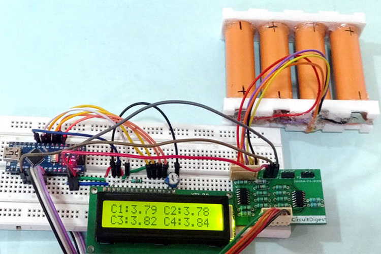
moving forward with this, I've a 4 channel voltage sensor reading the cell voltage, all seem pretty solid @ 3.298V per cell on a fluke DMM, the ads1115 voltage sensor has a resister ladder to drop dwn the voltage a bit, after calibrating it seems pretty good but with maybe 1 or 2 mV noise - what sort of accuracy do other BMS's have compared to a reliable meter?

also, the cell voltages don't seem to react all the same when getting a few amps current from a solar panel, only about 20mV difference but I expected a more uniform response somehow - is this usual? Overall monitoring seems to work though ?

Cell differences like that could be due to bad connections. A dirty cell terminal surface or a fastener that isn't tightened down could be to blame. Check the easy things (connections) first.
So obvious! ? Just testing to see what works so connections weren't torqued up. Solved 3 cells, but cell 1 is (I think) reading low with the voltage drop along the neg wire as same wire powers the eps32 doing the measuring. Something odd going on anyway...Cell differences like that could be due to bad connections. A dirty cell terminal surface or a fastener that isn't tightened down could be to blame. Check the easy things (connections) first.

Edit - Workaround seems to work, attach the ground from the ads1115 voltage sensor direct to the battery, it only draws uA so seems to be reading much more accurate now ?

Last edited:
That's a pleasant change!
Not quite there yet but looking much more useful ?That's a pleasant change!

Having another play with this , quick question for the boffins ...
Looking deeper into the ADS1115, seems to keep everything happy Vcc to that chip should be same as the ESP, 3.3v which means max measurement input of just over 2v.
So to get the voltage down, is it worth fitting an opamp to each cell, or just use a resister network?
Voltage out of the opamps will need to be dropped down anyway so I'm tending towards just resisters. Any thoughts?
tia
I recommend using your op-amps as true differential amps so you can remove the voltage offset of each cell.
You may find some useful info here and you can see an implementation here (the BOBMS1630 schematic in attachment).
I finally changed the topology and opted to put the multiplexer in front of the op-amps so I can have only one op-amp for 8 cells instead of 8 of them. You can see the current schematic here but be warned if you decide to add the caps on the inputs as in the schematic they must be before the resistors, not after (the current schematic needs an update to correct that).
Altho for 4 cells I wouldn't bother with a mux and I would just put 4 op-amps as it's much simpler and easier")
You may find some useful info here and you can see an implementation here (the BOBMS1630 schematic in attachment).
I finally changed the topology and opted to put the multiplexer in front of the op-amps so I can have only one op-amp for 8 cells instead of 8 of them. You can see the current schematic here but be warned if you decide to add the caps on the inputs as in the schematic they must be before the resistors, not after (the current schematic needs an update to correct that).
Altho for 4 cells I wouldn't bother with a mux and I would just put 4 op-amps as it's much simpler and easier
Thanks so much for the quick help, having a look at this design as well, little extra costs from easyeda so opamps seems the sensible way to go.I recommend using your op-amps as true differential amps so you can remove the voltage offset of each cell.
You may find some useful info here and you can see an implementation here (the BOBMS1630 schematic in attachment).
I finally changed the topology and opted to put the multiplexer in front of the op-amps so I can have only one op-amp for 8 cells instead of 8 of them. You can see the current schematic here but be warned if you decide to add the caps on the inputs as in the schematic they must be before the resistors, not after (the current schematic needs an update to correct that).
Altho for 4 cells I wouldn't bother with a mux and I would just put 4 op-amps as it's much simpler and easier
EasyEDA(Standard) - A Simple and Powerful Electronic Circuit Design Tool
EasyEDA is a free and easy to use circuit design, circuit simulator and pcb design that runs in your web browser.
Multicell Voltage Monitoring for Lithium Battery Pack in Electric Vehicles
In this article we will learn how we can measure the individual cell voltage of the cells used in a Lithium battery pack. For the sake of this project we will use four lithium 18650 cells connected in series to form a battery pack and design a simple circuit using op-amps to measure the...
 circuitdigest.com
RCinFLA
Solar Wizard
- Joined
- Jun 21, 2020
- Messages
- 3,559
Using a latching relay for a BMS cutout switch is risky. If you don't have enough power to de-latch relay you don't disconnect.
For a non-latching relay you then have the constant relay coil power. Typically, about 1 to 2 amps constant drain for a high current relay. The relay coil also gets pretty hot.
Some BMS's with contractor relay back down relay coil voltage after they engage relay to save current. This also reduces hold in force on relay contacts. This would likely not be good for a boat getting jarred from waves causing possible relay contact bounce.
Last edited:
Thanks. Interesting, hadn't thought of that. Though not sure lack of power to change the latch state is more likely to fail than constant power to keep a one latched. Both will need some sort of switching from the esp3.3v output. Since you obviously know a lot more than me ? , is there a rule of thumb for diode power sizing on the control of the relay to protect the control pin from voltage spike when the relay turns off?Using a latching relay for a BMS cutout switch is risky. If you don't have enough power to de-latch relay you don't disconnect.
For a non-latching relay you then have the constant relay coil power. Typically, about 2 amps constant drain for a high current relay.
Some BMS's with contractor relay back down relay coil voltage after they engage relay to save current. This also reduces hold in force on relay contacts. This would likely not be good for a boat getting jarred from waves causing possible relay contact bounce.
TIA
I tried the resistor divider network to measure cell voltages and then subtract measurements to acquire cell 2, 3 and 4 voltages. It didn't work for me. It's not accurate. I then switched to BiduleOhm's design. Let the OpAmp do the subtraction. That's been working well now for almost 2 years.So to get the voltage down, is it worth fitting an opamp to each cell, or just use a resister network?
Voltage out of the opamps will need to be dropped down anyway so I'm tending towards just resisters. Any thoughts?
tia
Cal's DIY BMS
RCinFLA
Solar Wizard
- Joined
- Jun 21, 2020
- Messages
- 3,559
There are random inverter current levels happening based on inverter load changes that will affect cell voltage. If you have significant time delay multiplexing between cell voltage readings, you get some readings with differing amount of high inverter current induced offset affecting the amount of cell voltage offset.
Most BMS's do a muxed parallel capacitor stored snapshot on all cells to capture the cell voltages at same instant in time, then time multiplex these caps down to microcontroller ADC base voltage to be serially round-robin voltage read.
All balancing is momentarily suspended when cell voltage snapshot is made so individual cell balancing current does on corrupt cell voltage reads. The sense voltage/balancing current wires are small gauge and long length, so you do not want balancing current flowing through the sense wires when making cell voltage measurements.
A sinewave inverter DC current will have a sizable amount of 2x AC line frequency ripple current that will show up on any battery line current measuring shunt resistor. The shunt voltage output must be filtered to average out this ripple to get to average DC current. It has less than 1 Hz filtering corner frequency. It can be done by analog R-C filter but requires a fairly large value filter capacitor or done with digital filter in microcontroller filtering ADC data. If done digitally, the ADC input will see a peak level representing up to twice the average DC current.
As with many things, the devil is in the details and doing things for the first time is prone to making mistakes.
Thanks for the reply, interesting.There are random inverter current levels happening based on inverter load changes that will affect cell voltage. If you have significant time delay multiplexing between cell voltage readings, you get some readings with differing amount of high inverter current induced offset affecting the amount of cell voltage offset.
Most BMS's do a muxed parallel capacitor stored snapshot on all cells to capture the cell voltages at same instant in time, then time multiplex these caps down to microcontroller ADC base voltage to be serially round-robin voltage read.
All balancing is momentarily suspended when cell voltage snapshot is made so individual cell balancing current does on corrupt cell voltage reads. The sense voltage/balancing current wires are small gauge and long length, so you do not want balancing current flowing through the sense wires when making cell voltage measurements.
A sinewave inverter DC current will have a sizable amount of 2x AC line frequency ripple current that will show up on any battery line current measuring shunt resistor. The shunt voltage output must be filtered to average out this ripple to get to average DC current. It has less than 1 Hz filtering corner frequency. It can be done by analog R-C filter but requires a fairly large value filter capacitor or done with digital filter in microcontroller filtering ADC data. If done digitally, the ADC input will see a peak level representing up to twice the average DC current.
As with many things, the devil is in the details and doing things for the first time is prone to making mistakes.
Not completely first time, just quite new with lots to learn ?
I've made battery capacity testers before to check cheap ebay 18650's, that needed filtering to take out the noise from pwm constant current control. Shows up on the oscilloscope. Didn't think to check with the 3k inverter running though.
The read voltage command is in one loop in micropython with nothing else on an ESP32 , should be pretty fast but maybe less internal averaging in the ADS would be a good idea to speed up the read time.
RCinFLA
Solar Wizard
- Joined
- Jun 21, 2020
- Messages
- 3,559
The PWM switching noise is small compared to 120 Hz sinewave ripple current.I've made battery capacity testers before to check cheap ebay 18650's, that needed filtering to take out the noise from pwm constant current control. Shows up on the oscilloscope. Didn't think to check with the 3k inverter running though.
For a 60Hz sinewave inverter it is a 120Hz sinewave that has a peak to peak valve of almost twice the average inverter DC current. The battery sees peak current of nearly twice the average DC current due to this 2x AC line frequency ripple current. This ripple current can be used to measure cells' impedance and some BMS's do this. The sampling rate of cell voltage must be greater to make the cell impedance measurements.
Inverter battery line electrolytic caps are for PWM switching frequency currents and have little effect on the 120 Hz ripple current, even down to moderately low AC load on inverter. It would take unrealistically low ESR supercaps in the 3 to 5 Farad range to have an impact on this 120 Hz ripple current for a 5kVA sinewave inverter. The most electrolytics capacitance on inverter battery line is about 0.1 Farad (Xantrex XW6848 inverter). Typical 5kVA HF all-in-one inverter has three or four 4700 uF (0.02 Farad for four in parallel) caps on battery line.
My battery/BMS is located in a motor home. There's huge temperature swings throughout the day. I couldn't get the temperature drifts under control when subtracting one measurement from another. The differential opamp configuration doesn't have that problem.
If you're looking for a GPIO driver then SI2302 is a very nice low voltage mosfet that will work with 3.2V gate drive.
If you're looking for a GPIO driver then SI2302 is a very nice low voltage mosfet that will work with 3.2V gate drive.
Similar threads
- Replies
- 44
- Views
- 2K
- Replies
- 3
- Views
- 189
- Replies
- 2
- Views
- 294