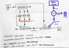
I'd like to deploy a UPS system as shown below. My primary need is the setup shown in black, a simple setup feeding directly to my equipment. The transfer switch is 15A which is more than I need.
Considering the black setup:
1. At point "A", what can I use to isolate the batteries? I assume I need this to prevent inter-battery current fllow?
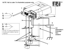
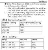
2. Also at point "A" or after, what breaker(s) can I use to limit amps and damage to the inverter? On page 11 of its manual, it states a 250A ANL fuse but I'd rather use a breaker.
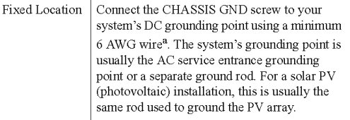
3. How do I ground the charger and inverter (G1, G2)? The manuals only speak of DC ground, as in a vehicle. Can I just use the AC ground? Wire size?
My optional need is to feed three 15A circuits from the main panel through this setup. Note that the total amp load of all three of these curcuits is only 10A, if that. The blue setup shows one feed off the UPS APC transfer switch. The APC has several female outputs, again, 15A total output. My desire here is to have a switch to select between the UPS setup and the main panel. This will allow me to switch to the main if I need to service the UPS:
4. What should I use for the select switch(es)?
5. If a subpanel is more appropriate here, feeding off one APC output, please advise on how to wire that up.
Some information on the equipment:
Charger is Xantrex TC 4012: owner's manual
Inverter is Xantrex ProWatt SW 2000: owner's manual
Batteries are Lifeline GPL-31XT AGM: data sheet
Although I can probably use an all-in-one unit charger/inverter, I already have this equipment so would like to put it in use.
If I am overthinking this solution, please advise.


