


You are using an out of date browser. It may not display this or other websites correctly.
You should upgrade or use an alternative browser.
You should upgrade or use an alternative browser.
hoping for some help on how to wire up a second shunt to monitor my DC load
- Thread starter harley
- Start date
Ampster
Renewable Energy Hobbyist
My DC shunt is inline on the negative. Did your shunt come with directions?hoping for some help on how to wire up the shunt as I cannot get anything to work..
Ampster
Renewable Energy Hobbyist
Is the shunt installed and wired to the meter and is the meter powered? Is it part of the battery monitor?
Jeffjeeptj
New Member
- Joined
- Mar 28, 2020
- Messages
- 53
Harley,
Is your goal to have a “specific for DC load” monitor in addition to your existing “summary” monitor? I think that is what I read.
I place an inline volt and amp device (essentially identical to the ones Will uses in his videos) to measure any specific load, whether an individual device or the total set of loads.
@Ampster - yep all wired and powered.
@Brewman (sorry about the delayed response here, I'm Australia and was asleep when you messaged back) - yes! that is exactly what I'm trying to achieve. I'm using this Renogy for the 'summary' battery monitor and the same Bayite monitor as you are for my 'total load' monitor. The problem I'm having is when I have tried integrating the 'total load' monitor into my test circuit, the 'total load' monitor only every reads a tiny fraction of the actual load amps - in fact it seems to just be "stealing" from the summary monitor e.g if the battery summary monitor was showing 5A prior to connecting in the 'total load' monitor, once the 'total load' monitor is connected it might show 0.2A, but the battery 'summary' monitor now shows 4.8A.
I should add that my test circuit has been sans charge controller. My test circuit has been simple: battery to a control/ switch box with negative bus bar and fuse box with fridge connected (thought a simple testing circuit like this would be best, but maybe not including my Renogy DC-DC into the circuit is part of what is creating an inability to get this setup working correctly???)
yep all wired and powered.Is the shunt installed and wired to the meter and is the meter powered? Is it part of the battery monitor?
(sorry about the delayed response here, I'm Australia and was asleep when you messaged back) - yes! that is exactly what I'm trying to achieve. I'm using this Renogy for the 'summary' battery monitor and the same Bayite monitor as you are for my 'total load' monitor. The problem I'm having is when I have tried integrating the 'total load' monitor into my test circuit, the 'total load' monitor only every reads a tiny fraction of the actual load amps - in fact it seems to just be "stealing" from the summary monitor e.g if the battery summary monitor was showing 5A prior to connecting in the 'total load' monitor, once the 'total load' monitor is connected it might show 0.2A, but the battery 'summary' monitor now shows 4.8A.How I do it.
I should add that my test circuit has been sans charge controller. My test circuit has been simple: battery to a control/ switch box with negative bus bar and fuse box with fridge connected (thought a simple testing circuit like this would be best, but maybe not including my Renogy DC-DC into the circuit is part of what is creating an inability to get this setup working correctly???)
Ampster
Renewable Energy Hobbyist
The way I figured out those kind of things is to draw a picture and trace the current through the device i want to measure and make sure have the shunt in the right place.
Thanks for your help so far. Ok a bit of progress - I've got both meters now showing correct and current Amps. But, I think they could both just be showing the draw on the battery. I'll try and getting a diagram of wiring going now.Do you have a circuit diagram or at least a picture of your wiring?
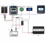
@Brewman here's what i have got so far as a wiring diagram

My test circuit is currently all of what is shown this diagram, with the exclusion of the car/starter battery and associated switch. With this setup I've now got the correct amps showing on both the battery monitor (Renogy monitor, not shown in diagram) and the total DC load monitor (bayite, not shown in diagram). So at this stage still a few questions:
How does that look to you? Does it look like the DC load monitor would be showing the total DC load? or is it actually just wired up as a second battery monitor (which I don't need") )
)
As I don't have my solar panels yet I couldn't work out how to add more DC load (powered by a separate battery) to test if the two monitors are actually going to report different Amps. I've got a couple of small 6V lead acid batteries (from my kids little electric cars) to play with, but I was shorting the circuit out with what I tried - any idea how I could test?
After I get these two monitor running they way I want them and my solar panel arrives, I'll need to work out how to wire in the solar shunt/monitor (a 2nd Bayite - shown in the current wiring diagram, but not wired in).
My test circuit is currently all of what is shown this diagram, with the exclusion of the car/starter battery and associated switch. With this setup I've now got the correct amps showing on both the battery monitor (Renogy monitor, not shown in diagram) and the total DC load monitor (bayite, not shown in diagram). So at this stage still a few questions:
How does that look to you? Does it look like the DC load monitor would be showing the total DC load? or is it actually just wired up as a second battery monitor (which I don't need
)As I don't have my solar panels yet I couldn't work out how to add more DC load (powered by a separate battery) to test if the two monitors are actually going to report different Amps. I've got a couple of small 6V lead acid batteries (from my kids little electric cars) to play with, but I was shorting the circuit out with what I tried - any idea how I could test?
After I get these two monitor running they way I want them and my solar panel arrives, I'll need to work out how to wire in the solar shunt/monitor (a 2nd Bayite - shown in the current wiring diagram, but not wired in).
Last edited:
Renogy thing uses 500 amp shunt. The Baylight thing uses a 100 amp shunt. Are you measuring the same circuit? the same current? I would find a general amp meter that uses a 500 amp shunt and share the Renogy shunt.
Or this.= https://www.amazon.com/Yeeco-Voltme...amp+meter&qid=1593205743&s=industrial&sr=1-11
Or this.= https://www.amazon.com/Yeeco-Voltme...amp+meter&qid=1593205743&s=industrial&sr=1-11
Similar threads
- Replies
- 19
- Views
- 577
- Replies
- 91
- Views
- 2K