diy solar

diy solar

Horsefly's Cabin Solar LiFePO4 Upgrade

Horsefly

Solar Wizard
Joined
Dec 12, 2020
Messages
1,820
Location
Denver, mostly
Our family cabin was built in the 1970's, at about 9,000 feet elevation in the mountains of Colorado. It was wired (by teenage me) for 120VAC even though there was no possibility of grid power. We had a generator that we ran when needed, such as to run the well pump or for lights. By 2017, my co-owners of the cabin (sister and brother) agreed to put in solar. I was 4 years post-retirement, and was egging to do some small amount of engineering, so I dove in.

Our original energy budget was for a worst case of 3,300Wh per day, and a maximum possible instantaneous load of a bit under 3,000W. Both have since appeared to be overly conservative, but that's OK. I went with a 24V system, and used the following components:
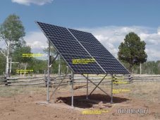
  • 6 x Canadian Solar 280W panels, on a ground mount with a 200 ft run to the solar room equipment. Wired in two strings of 3 panels to combiner box on the ground mount.
  • Schneider CSW4024 Inverter. Pure sine wave, split phase, 3,600W continuous, 7,000W max surge
  • Schneider MPPT60-150 Solar Charge Controller. 150V max input, 60A max output.
  • Schneider System Control Panel (SCP) to program the inverter and SCC.
  • 4 x VMax XTR155 12V, 155Ah AGM batteries, wired into a 2s2p, 24V configuration.
  • Midnite Solar E-Panel designed for the CSW4024.
  • Various breakers, surge protection devices, and wiring.
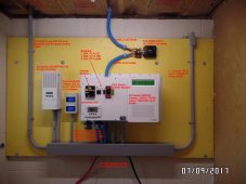
The electronics and the solar array are shown here:
Annotated_Electronic_backboard.jpg
Annotated_Ground_Mount.jpg

At the time I looked at LiFePO4 but felt I didn't know enough and was not sure how to handle the temperature issues. We went with the relatively cheap VMax AGM batteries, and they have actually performed fairly well. However, the voltage "sag" when they are under load and how quickly the resting voltage drops during the evening seems to indicate the battery bank is way below the 310Ah capacity that it supposedly started with.

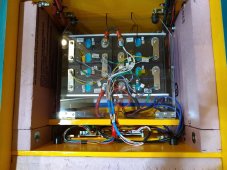
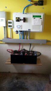
Here's the current battery shelf below the other electronics, including the 4, 90lb AGM batteries (sorry for the bad focus - I must have been drinking):battery_shelf.jpg
The story continues....
 
Last edited:
Last year (2020) all the travel that my wife and I had planned got cancelled, and I found myself with way too much time. I revived the thinking about LiFePO4 batteries for our system.

I somehow found the DIY Solar Forum late in 2020, and joined in January 2021. I read through tons of threads of the trail blazers building DIY systems and I noted all the issues and ideas everyone had. Using the knowledge picked up here, I started thinking about what our upgrade would look like:
  1. Our nameplate 310Ah AGM battery bank met our original energy budget with 155Ah (50% DoD), and no days of autonomy. At the time, we figured we had been used to using the generator for 40 years, and if it was every so dreary at the cabin that the solar didn't recharge the batteries, we would just fall back to the generator. So at a minimum we needed about 155Ah of usable capacity.
  2. Our 6 x 280W panels was an intentional over design in 2017. It is very sunny at our cabin, and according to NREL we should get an average 5.8 hrs of peak sun per day (more during the months the cabin is used). 6 x 280 x 5.8 = 9.7kWh per day. The math says this is more than enough to service a battery bank larger than our 155Ah (50% DoD) limit. I figured a LFP battery of either 230Ah or 280Ah 8S would probably be fine.
  3. If we are to leave a LiFePO4 battery at the cabin over the winter, we needed to come up with how we would keep them warm. Our standard operating mode for the winter with the system was to leave the SCC on but put the inverter in standby and turn off all the DC loads. For our LiFePO4, this mode would provide daily power (except when the panels are covered with snow) for some heat for the battery.
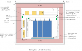
Thinking about keeping the LiFePO4 cells warm, I posted a thread here and got more feedback. This gave me the basics for a design. Here's the drawings of the box I made:
LFP_Cell_Layout3_230Ah_Box_Side_View2.png

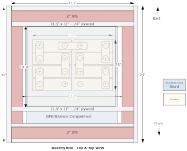
The top of the box was to be removable, but the bottom and sides were all glued and attached with pocket screws. A top shelf on the inside would hold the control electronics as well as the two shunts I put into the system. The controls would be mostly about powering the heating pads that were beneath the cells, attached to an aluminum sheet. The top shelf of electronics is hinged, and lifting it up exposes a Lexan window over the cells, protecting them from an accidental short. This shelf is hinged the other way, to allow working on the LFP pack. A pocket compartment on the front side houses a 1/2" plywood shelf holding the BMS and the Active Balancer.

Here's the drawing of the top view:
LFP_Cell_Layout3_230Ah_Box_TopView_w_covers.png
I decided to put the box on casters. With the casters on, the box is about 2' on each side.

Next up: The electrical design.
 
Based on my "On Keeping LFP Warm" thread (here) and @Will Prowse's "LiFePO4 Heating Pad for cold temperatures" (here). I came up with a few requirements:
  1. Heating pads - I experimented with several different DC heating pads from Aliexpress and Amazon. I ended up with 12V, 12W heating pads with a relatively low (60°C) max temperature.
  2. By mounting the heating pads on an aluminum plate, I can dissipate the heat so that it warms an area more uniformly.
  3. I would put silicone pads (kitchen trivets) under the heating pads, to prevent the heat from damaging the XPS insulation.
  4. I needed an electronic thermostat to set the desired temperature of the cells, and turn enable the power to the heating pads. I will probably set this thermostat to about 55°F, at which point it will turn off. If the temp falls down to 45°F, it will turn back on.
  5. Several people expressed some concern about the heating pads warming too quickly, potentially damaging the cells close to the heating pad before the rest of the cells were warm. So I added a second thermostat that would set a limit for the heated aluminum plate under the cells. This thermostat will turn off if the plate gets up to 95°F, and turn back on when the plate temp has fallen down to around 80°F.
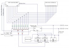
  6. Forum member @diyernh pointed out another safety precaution. If the battery level falls below a certain level, we want to avoid using power from the battery to heat the cells, otherwise, we could warm the cells but in the process end up with a fully depleted pack. I found the Thronwave Labs PowerMon-5s could turn off a relay if the voltage falls below a certain level. So I used the PMon-5s to control an SSR, turning it on if the voltage is above 26V, or off if it falls below that. Thus the heating pads would get power only if the both thermostats are on, and the voltage is seen as above 26V.
Here's the schematic for this:
Schematic.jpg

So in practice I think this is how this will work:
  1. If the temperature measured on the top of the cells falls below 45°F, thermostat 1 will turn on, and stay on until the temp reaches 55°F.
  2. If the temperature of the aluminum panel beneath the cells (and above the heating pads) is below 80°F, thermostat 2 will be on. When the aluminum reaches 95°F thermostat 2 will turn off.
  3. Thermostat 2 may cycle on and off several times before the temperature on the top of the cells reaches 55°F.
  4. If there is no sunlight, the battery itself will power the warmer circuit. However, if the battery ever falls below 26V, the heating circuit will be disabled. When the SCC fires up with power from PV, the voltage should rise back up above 26V, enabling heating again.
Next up, building the box.
 
Just about two months ago (mid-June, 2021), I started building the box. I bought a 4' x 8' sheet of 3/4" plywood, a 4' x 4' sheet of 1/2" plywood, and a 4' x 8' sheet of 2" XPS insulation. And the game was on.

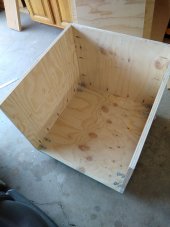
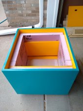
Here's the box with three sides and the bottom:
IMG_20210625_152930354.jpg
The sides and the bottom were glued and joined with pocket screws. I didn't use glue anywhere else, as I wanted to leave open the possibility of taking things back apart and changing the design if needed. Notice I had attached casters on the bottom of the box, with the two front casters being lockable.

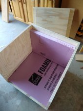
Here's the box with the same 3 sides and bottom, but with XPS laid into the bottom and on the back wall:
IMG_20210625_153005502.jpg

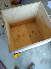
Here's the completed outside frame of the box. Then I put the glue away:
IMG_20210625_155326993.jpg

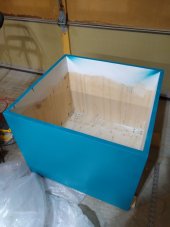
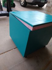
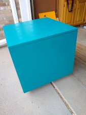
With the consultation of my wife and daughter, we settled on a blue exterior (Rust-oleum "Lagoon") and yellow interior (Rust-oleum "Golden Sunset") for the box. Here's a first coat on the outside walls of the box:
IMG_20210628_221608669.jpg

Not shown in this sequence was the sanding, applying sheetrock joint compound, more sanding, and eventually a coat of white primer.

Next I started doing some of the interior of the box. Here's after putting the bottom (including a small sheet of 1/8" hardboard panel) and a 1/2" plywood back interior wall (excuse my feet):
IMG_20210629_215926666.jpg


More to come.
 
Last edited:
As I mentioned early, I was building a pocket area with a board to hold the BMS and Active Balancer. Here's a pick with that small board held in by a couple of latches that are usually used for window screens:

IMG_20210704_164836742.jpg

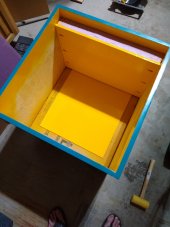
Here's with the next layer of wall to define the BMS / Balancer pocket, and the 1/4" aluminum plate on the bottom of the box:
IMG_20210706_154858943.jpg

And here's the box with the remaining back wall to the box:
IMG_20210706_154904966_HDR.jpg

And the view from the front of the box:
IMG_20210706_154920768.jpg

Here I've got the top propped up on part of the XPS that lines the inside of the cover:
IMG_20210706_155001973.jpg
 
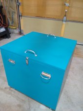
Here's the box with the top on:

IMG_20210706_155030149.jpg

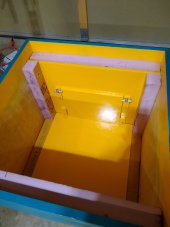
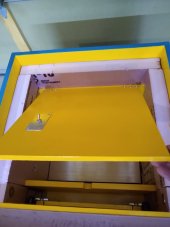
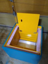
Then I started working on the inside details of the box. The hinged panel near the top of the box is where all the electronics goes. Here's that panel in the down position, part way up, and all the way up:
IMG_20210708_084359975.jpg

IMG_20210708_084417267.jpg

IMG_20210708_084709567.jpg

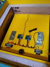
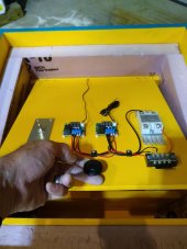
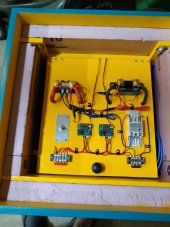
Then I started wiring the electronics:
IMG_20210806_135427096.jpg
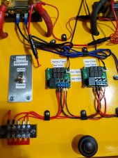
Here left to right across the top are the switch to enable the heating controls, the thermostat to set the desired temp for the cells, the thermostat to set the limit temp for the heating plate, and the SSR which will turn off the heating if the battery gets below 26V. The two strips on the lower left and right are +24V power and ground. In the middle is a handle to lift the panel.
 
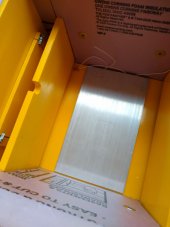
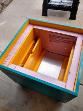
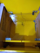
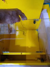
Under the top hinged panel is a hinged Lexan sheet that allows the cells to be seen but protects them from dropping tools and causing shorts. Here's three shots of lifting the top panel to expose the Lexan, and lifting the Lexan on its hinges.
IMG_20210806_140621091.jpg

IMG_20210806_140628505.jpg

IMG_20210806_140647172.jpg

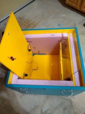
Here's a side view with both of the two hinged panels up:
IMG_20210806_140717511.jpg

Note that I later had to angle cut the corners of the Lexan to allow for wires (you'll see that at the end).
 
Will you be able to access that panel for the BMS without removing the batteries from the enclosure?
 
Will you be able to access that panel for the BMS without removing the batteries from the enclosure?
Yeah, sorry that wasn't clear. The idea of the position of panel where the BMS and Balancer are mounted is that they can be accessed just by lifting up the top panel. The second panel (the clear Lexan) is hinged in front of the "pocket" where the BMS / Balancer are mounted, so it is not in the way.
 
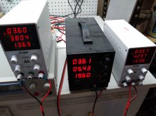
About this time I received my 8 x 230Ah EVE cells via @Michael B Caro. That shifted my attention for the moment away from the box itself. I wanted to test all the cells for capacity. I have 3 cheap and 1 mid-priced bench power supplies (the fourth one is in the lower left of this photo, but doesn't have a bright display):
IMG_20210809_192616151.jpg

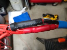
I made 14 AWG red/black cables with ring connectors on each to connect to the power supplies. Each of the red-display units was one of the cheap 30V/10A CV/CC power supplies on Amazon. The lower-left one was a bit better 30V/20A supply from Circuit Specialists. The 20A supply hookup was on the back of the box.

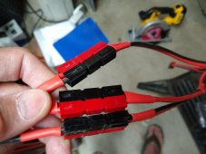
On the other end of the red/black pairs I had Anderson power pole connectors, which are great for this purpose. Then I had 4 power pole connectors on the other side that merged (via a butt connector) into a 10 AWG cable to another set of ring terminals that would connect to cells. This allowed me to charge a cell with 4 parallel power supplies with up to 40-50A.

IMG_20210809_192639795.jpg
IMG_20210809_192656884.jpg

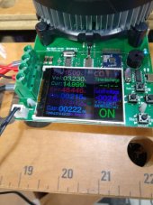
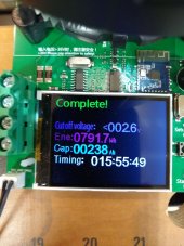
I started doing a capacity test on each cell via one of the small 180W testers on Aliexpress. It was a very capable little tester, that I would recommend for anyone not wanting to waste lots of money on a capacity tester. (Note: This tester was sold to @chrisski who is now using it, and for all I know he will sell it again when he is done!)
IMG_20210812_065200078.jpg
IMG_20210812_075927182.jpg

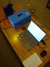
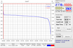
As I started to do the testing via the little tester, my REAL tester arrived from China. It is the EBC-A40L "High Current" battery tester. It can charge a cell at up to 40A, discharge a cell at up to 40A, and it has really GREAT PC software that lets you control and collect data on either. Andy on the "Off Grid Garage" channel on YouTube showed it, and I knew I had to get it. The shipping was almost as much as the cost of the product, but it was worth it. So I ended up testing the other 4 cells with the new ECB-A40L.
IMG_20210815_154657796.jpg

Here's a graph from the test of one cell.

7Cell5CapacityTest.PNG
 
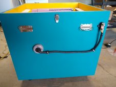
I spent some time working on the outside of the box, putting handles on the lid, handles on the side, and clasps to hold down the lid (not sure why those are needed, but it seemed cool to do):

IMG_20210806_135334910.jpg

I went back to finishing the wiring of the internals of the battery box. Based on the electronic design (see above) I had to mount the Victron Smart Shunt and the Thornwave Labs PMon-5s, and it only made sense to mount them on the top panel.
IMG_20210818_123848974.jpg

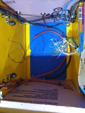
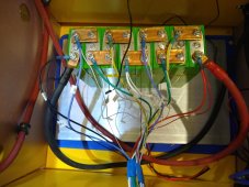
That meant I had some relatively heavy 2 AWG wire (2 red, 2 black) coming off this hinged top panel to go down into the box. That required a minor modification to my original design, as I had to cut off the corners of the Lexan so the wires could fit. Didn't turn out to be a big issue.

Now I had to provide wiring from the inside of the box out to the outside of the box, where the box would hook up with the rest of our cabin system. That required me to drill holes into the nicely finished box that I had worked on for days! So I drilled holes through 5 coats of polyurethane and 4 coats of paint. Ugh!


IMG_20210818_123956064.jpg
The above pic shows the inside wiring from the left side. The red cable is going out to the left side of the box (bottom in this box), and black cable is going out to the right side (top in this pic) of the box.

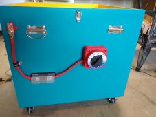
Here's the outside of the box on the left side, where the RED / positive connection will be made to the rest of the system. I know this is an ANL fuse, and I will probably get grief for doing that vs at Type T fuse. Oh well. The Type T was too big!
IMG_20210821_172825488.jpg
The Perko switch includes a 10 Ohm, 50W resistor for pre-charging the inverter.

And here is a pic of the right side where the negative will hook up to the system:
IMG_20210821_172847010.jpg
 
Man, you sure do great and neat job, very impressive.
BTW, where did you get that gray rectangular junction box from?
 
Man, you sure do great and neat job, very impressive.
BTW, where did you get that gray rectangular junction box from?
Gray rectangular... I'm not sure where you are referring. I've probably got links I can give to most stuff, but you'll have to help me find where you are talking about.

But, thanks for the compliment!
 
The gray metal junction box in picture #1 in your post #1.
I have been looking for it at Home Depot and Lowes, but no luck.
 
Last edited:
The gray metal junction box in picture #1 in your post #1.
I have been looking for it at Home Depot and Lowes, but no luck.
Are you talking about the kinda big 4 ft long box below all the stuff we installed in 2017? That's referred to by multiple names: A "wireway" or "wire trough". I think I got that one from Zoro, but several of the commercial houses carry it. Look to Zoro or Grainger. That one is a 4" x 4", 4 ft long wireway. I think it was about $45 back in 2016/2017 when I bought it.
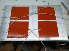
 
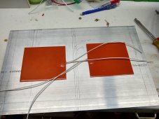
The heating pads I chose (after experimenting with lots of heating pads) were some 12V, 12W pads I got from Aliexpress. Two of these in series work with my nominal 24V battery, drawing around 1A (24W). Although I'm not sure how much heating I will need, I am going to try 2 pads at first, but if it turns out I need more there is room on the aluminum sheet for 4, which would be 2s2p of the pads, drawing 2A at 24V, or about 48W.

IMG_20210818_200902201_HDR.jpg

IMG_20210818_200837760.jpg

Once I got everything wired up, I wanted to test it before I went through the trouble of plugging in my big 230Ah cells. I used my "practice" pack of 8s 25Ah cells from BatteryHookup.com.
IMG_20210820_133759416.jpg

This allowed me to confirm my wiring worked as designed. So the thermostats and SRR controlled the heating pads.

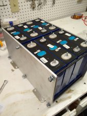
Meanwhile, I was pre-staging my 230Ah cells on my workbench.
IMG_20210820_220434360.jpg

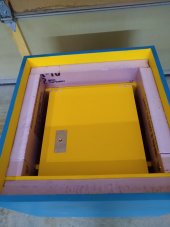
I finished labeling the controls, then put the "real" cells (8S 230Ah) into the box:

IMG_20210821_195929675.jpg

IMG_20210823_152646834.jpg

Note that you can't really see it, but the "heat plate" thermostat temp sensor is actually between the two rows of cells, at the bottom.

There's not a lot of room, but I have verified that I have room for 280Ah cells if I ever need to go that way.
 
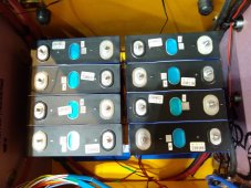
Finally, I put in the compression frame around the cells, tightened it down just enough, and hooked up the balance leads from the BMS and active balancer to the cells:

IMG_20210824_134032287.jpg

Here you can see the Active balancer on the left bottom, the BMS on the right bottom, and the balance leads going through the notch in the wall under the Lexan hinged panel.

I've been running the pack through it's paces. I've tried some 25A loads and found a couple of places where the cells were not staying balanced, but once I tightened some of the nuts I got them all balanced pretty well.

My plan is NOT to put this in the cabin this winter. I need to see how this works, and if 2 heating pads needs to be upgraded to 4 pads. So my plan is to exercise this here at my home in Denver this winter. I've purchased some logging sensors so I can collect stats on the temperature outside the box, inside the box, and how often the heating pads are turned on to maintain a happy temperature. If all goes well, everything will get loaded up and hauled to our cabin next spring! Only problem is that it is about 150 lbs, so I may need help!
 
Back
Top