Greetings and thank you for having this forum, Will E. P. I have a question concerning keeping separate battery banks, monitoring them, and keeping them charged.
1. I can not afford solar yet, no matter how cheap the panels may be. That is a sad but relevant fact.
2. Necessity mandates that I make do with what I have and what I can reasonably obtain, given my current financial and physical limitations.
3. I value knowledge and appreciate its sharing.
4. Within a matter of possibly only a few months, I will be forced to live in my minibus, which is not yet fully converted into an RV.... but is in process thereof.
5. It came with four batteries. ALL are regular 'start' batteries and not a single one is deep cycle. I can NOT yet afford to replace any of them. They are paired in parallel and the pairs are in separate locations. One set is beneath the bus... and it is this set that cranks the bus... I believe folks tend to refer to the location as 'the basement'. The other set is up under the hood, installed by the previous owner on a platform they rigged up... it is ugly but sturdy... so I can't complain.
6. I will refer to the basement set as the START bank and the hood set as the HOUSE bank.
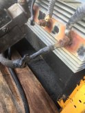
7. At present both banks are attached to what I believe is a 'battery isolater'.... it is very old looking and difficult to see any mfg. info, let alone details. I suspect it is an isolater because it has three bolts.... 1, ALT, 2...... with connected leads.... position one leads to the House Bank, Alt leads 'down and out of sight' , as does the line on 2 position. Another clue that the apparatus is a battery isolater is that the previous owner made a passing comment that the House and Starter Banks are both charged when the vehicle is driven.
8. Thankfully and yet oddly, at the time (since I am a complete beginner, as of the purchase of this rig) the House battery has a cable that runs into the bus and into a old style RV control panel.... a Megatek 45amp panel. I am thankful that it was included but confused initially as it was NOT connected to anything!! No shore power receptacle, let alone to actual shore power. Included WAS a 30amp shore power lead. Despite NOT being connected to shore power.... that House Battery was connected to the fuse panel and the fuse panel had ONE item connected to it... a driver's fan... a nice heavy duty variable speed steel old timer type that can be aimed at the driver... which is better than nothing when driving down the road without air conditioning! The young couple I bought the rig from must have set that up that way so they could at least have air circulation while boon docked and working on the bus, without affecting the START Bank.
9. I suspect that the first place I will go, after having to move, will most likely be an RV camp, so I decided to get a 30a receptacle and install it so I can access shore power. That was a learning experience as I had to get a hole saw and drill through very tough school bus shell steel... heehee... and very rewarding when I succeeded!
10. Prior to hooking up the Megatek panel to shore power, I disconnected the House Bank, because internet research about that panel revealed that the charger was notorious for overcharging batteries. While those House batteries are NOT ideal for what I want to ultimately accomplish, they are what I have and hopefully will function at least temporally, if I am prudent. SO I SHOPPED ON EBAY and came across a deal on an upgraded Progressive Dynamics PD4655V Converter Charger with Intelli-power-wizardry..... it supposedly safely charges lead batteries. I got it really cheap because the housing was bent, it was missing a cable, the pins that cable were suppose to connect to were bent, and a large resistor was broken off. They normally sell for over $2oo and I got it for $51 and then when I pointed out to the seller that the ad said it came with everything the mfg provides, yet was missing that cable, they kindly gave me a partial refund, so I got it for about $40 dollars.
I looked up the mfg... Progressive Dynamics... to get the missing cable and broken resistor. straightening the metal case was easily done, had a old friend desolder the old resistor legs out of the board and soldered in the new resistor.... while I looked on to learn... and I gently bent back the bent pins. to plug in the cable that connects the 'wizard' to the fuse panel, where an led light indicates the charging mode.
I reconnected the House Bank to the Distribution Panel, which now has a new fuse panel as well, since it came with the upgraded converter charger.
I plugged in my shore power... with a ponytail for 15amp extension cord.
I put a cheap 'cigarette style' volt meter into a receptacle that has battery clamps, onto the House battery, which I had already used my volt meter on to determine that it was indeed low in charge. I flipped on the Distribution Panel Breakers and anxiously hustled out to look at that volt meter! To my relief... the charger seemed to be doing its job!
I continued to monitor the charging process and it went through all the phases that the literature claimed it would do! So I am delighted of course.
11. After watching one of your videos, I used part of my meager monthly 'luxury fund' (anything not spent on actual bills) which is also my food budget... to get one of those AlLi Battery Monitors with a 350a shunt. Maybe overkill on the shunt but I do hope to have a better battery bank in the future.
I think I understand how I would hook it up, to monitor the House Bank. The Shunt has to be the only thing connected to the Far Negative battery.... then all other negative things go to the other end of the shunt.
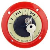
12. I also purchased on ebay a used locking Perko Switch... 1, 2, 1+2, Off and Lock..... JUST in case I need that somehow.
13. SOOOOO.... my question is..... can I have the shore line powered converter/ charger connected to BOTH banks, so the Starter Bank can be charged, either separately or together, with the House Bank? Would I do this with that switch, mentioned above... OR... with neg and pos Bus Bars with both banks coming into it on one side and going out to the Dist. Panel battery connections? There is NOT room for two sets of big wire to connect directly into those panel connectors.
14. ALSO... do you recommend that I use inline fuses on the battery cables?
I hope I have adequately described the electrical situation and my desire to have both banks charging when the vehicle is driven and ALSO both banks maintained with shore power charging.
IF YOU MADE IT THIS FAR, THANK YOU FOR YOUR KINDNESS IN DOING SO.
Any and all assistance is appreciated!
1. I can not afford solar yet, no matter how cheap the panels may be. That is a sad but relevant fact.
2. Necessity mandates that I make do with what I have and what I can reasonably obtain, given my current financial and physical limitations.
3. I value knowledge and appreciate its sharing.
4. Within a matter of possibly only a few months, I will be forced to live in my minibus, which is not yet fully converted into an RV.... but is in process thereof.
5. It came with four batteries. ALL are regular 'start' batteries and not a single one is deep cycle. I can NOT yet afford to replace any of them. They are paired in parallel and the pairs are in separate locations. One set is beneath the bus... and it is this set that cranks the bus... I believe folks tend to refer to the location as 'the basement'. The other set is up under the hood, installed by the previous owner on a platform they rigged up... it is ugly but sturdy... so I can't complain.
6. I will refer to the basement set as the START bank and the hood set as the HOUSE bank.
7. At present both banks are attached to what I believe is a 'battery isolater'.... it is very old looking and difficult to see any mfg. info, let alone details. I suspect it is an isolater because it has three bolts.... 1, ALT, 2...... with connected leads.... position one leads to the House Bank, Alt leads 'down and out of sight' , as does the line on 2 position. Another clue that the apparatus is a battery isolater is that the previous owner made a passing comment that the House and Starter Banks are both charged when the vehicle is driven.
8. Thankfully and yet oddly, at the time (since I am a complete beginner, as of the purchase of this rig) the House battery has a cable that runs into the bus and into a old style RV control panel.... a Megatek 45amp panel. I am thankful that it was included but confused initially as it was NOT connected to anything!! No shore power receptacle, let alone to actual shore power. Included WAS a 30amp shore power lead. Despite NOT being connected to shore power.... that House Battery was connected to the fuse panel and the fuse panel had ONE item connected to it... a driver's fan... a nice heavy duty variable speed steel old timer type that can be aimed at the driver... which is better than nothing when driving down the road without air conditioning! The young couple I bought the rig from must have set that up that way so they could at least have air circulation while boon docked and working on the bus, without affecting the START Bank.
9. I suspect that the first place I will go, after having to move, will most likely be an RV camp, so I decided to get a 30a receptacle and install it so I can access shore power. That was a learning experience as I had to get a hole saw and drill through very tough school bus shell steel... heehee... and very rewarding when I succeeded!
10. Prior to hooking up the Megatek panel to shore power, I disconnected the House Bank, because internet research about that panel revealed that the charger was notorious for overcharging batteries. While those House batteries are NOT ideal for what I want to ultimately accomplish, they are what I have and hopefully will function at least temporally, if I am prudent. SO I SHOPPED ON EBAY and came across a deal on an upgraded Progressive Dynamics PD4655V Converter Charger with Intelli-power-wizardry..... it supposedly safely charges lead batteries. I got it really cheap because the housing was bent, it was missing a cable, the pins that cable were suppose to connect to were bent, and a large resistor was broken off. They normally sell for over $2oo and I got it for $51 and then when I pointed out to the seller that the ad said it came with everything the mfg provides, yet was missing that cable, they kindly gave me a partial refund, so I got it for about $40 dollars.
I looked up the mfg... Progressive Dynamics... to get the missing cable and broken resistor. straightening the metal case was easily done, had a old friend desolder the old resistor legs out of the board and soldered in the new resistor.... while I looked on to learn... and I gently bent back the bent pins. to plug in the cable that connects the 'wizard' to the fuse panel, where an led light indicates the charging mode.
I reconnected the House Bank to the Distribution Panel, which now has a new fuse panel as well, since it came with the upgraded converter charger.
I plugged in my shore power... with a ponytail for 15amp extension cord.
I put a cheap 'cigarette style' volt meter into a receptacle that has battery clamps, onto the House battery, which I had already used my volt meter on to determine that it was indeed low in charge. I flipped on the Distribution Panel Breakers and anxiously hustled out to look at that volt meter! To my relief... the charger seemed to be doing its job!
I continued to monitor the charging process and it went through all the phases that the literature claimed it would do! So I am delighted of course.
11. After watching one of your videos, I used part of my meager monthly 'luxury fund' (anything not spent on actual bills) which is also my food budget... to get one of those AlLi Battery Monitors with a 350a shunt. Maybe overkill on the shunt but I do hope to have a better battery bank in the future.
I think I understand how I would hook it up, to monitor the House Bank. The Shunt has to be the only thing connected to the Far Negative battery.... then all other negative things go to the other end of the shunt.
12. I also purchased on ebay a used locking Perko Switch... 1, 2, 1+2, Off and Lock..... JUST in case I need that somehow.
13. SOOOOO.... my question is..... can I have the shore line powered converter/ charger connected to BOTH banks, so the Starter Bank can be charged, either separately or together, with the House Bank? Would I do this with that switch, mentioned above... OR... with neg and pos Bus Bars with both banks coming into it on one side and going out to the Dist. Panel battery connections? There is NOT room for two sets of big wire to connect directly into those panel connectors.
14. ALSO... do you recommend that I use inline fuses on the battery cables?
I hope I have adequately described the electrical situation and my desire to have both banks charging when the vehicle is driven and ALSO both banks maintained with shore power charging.
IF YOU MADE IT THIS FAR, THANK YOU FOR YOUR KINDNESS IN DOING SO.
Any and all assistance is appreciated!