diy solar

diy solar

How do I limit my SmartSolar charge controller to charging my battery bank at 99%

Off Gridin' It

New Member
Joined
Dec 11, 2020
Messages
102
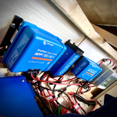
Here are some details of my system.
I have two SmartSolar charge controllers feeding one DIY battery.

Charge controller 1
SmartSolar 150/45 - Fed by a 1200 watt array on the roof of the camper.

Charge controller 2
SmartSolar 100/30 - Fed by a 500 watt ground deploy array
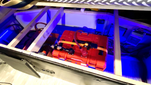
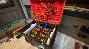
Battery Bank
6014 wh DIY battery - 24 volts
8S - Daly 250 amp BMS

I am getting a "Cell volt high level 2" fault alarm on the daly BMS.
The BMS turns off charging when this happens but otherwise is operating normally and once the charging backs off due to a load being put on the battery the fault clears and charging resumes.

The BMS cell voltage limit is set to 3.65 and the "Sum volt high protect" is set to 29.2.d
So it would seem the charge voltage from the Smart Solar charge controllers is exceeding the limit.
When only one charge controller is connected this doesn't happen.

But if I have used a lot of power overnight for some reason and I deploy the ground array to charge faster then once it reaches absorption I get the "Cel volt hight level 2" Fault.

((((MY QUESTION))))
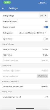
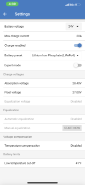
My question is can I tell one of the SmartSolar charge controller to stop charging at 99% so that it won't exceed the voltage limit? Should I set the float voltage lower? It is set to 27.00 volts now.
Or should I set the absorption voltage lower? It is set to 28.4.

@Guy Stewart (Victron Community Manager)
 
Can you post a pic of your SCC charging settings?

to stop charging at 99% so that it won't exceed the voltage limit?
Setting the charger to stop at battery level voltage is a lot different than cell level charging and BMS high voltage faults.

It sounds like you think that a lower charge current fixes this, so you can lower the charging amps on one or both units.

It may also take setting your charge voltages to a lower value. Are you assuming that 3.65Vpc is 100% SoC?
 
Can you post a pic of your SCC charging settings?


Setting the charger to stop at battery level voltage is a lot different than cell level charging and BMS high voltage faults.

It sounds like you think that a lower charge current fixes this, so you can lower the charging amps on one or both units.

It may also take setting your charge voltages to a lower value. Are you assuming that 3.65Vpc is 100% SoC?
3.65 is charge voltage. The limit in the BMS is set to 3.65. With one charge controller this is not exceeded and I don't get the FAULT. But with two charge controller I do. So but limiting one charge controller I believe it will stop the fault. The BMS is actually working properly and protecting the battery buy shutting off charging. This is why I want to limit one charge controller.
 
Can you post a pic of your SCC charging settings?


Setting the charger to stop at battery level voltage is a lot different than cell level charging and BMS high voltage faults.

It sounds like you think that a lower charge current fixes this, so you can lower the charging amps on one or both units.

It may also take setting your charge voltages to a lower value. Are you assuming that 3.65Vpc is 100% SoC?
 

Attachments

  • 150_45.PNG
    150_45.PNG
    308.4 KB · Views: 12
  • 100_30.PNG
    100_30.PNG
    308.7 KB · Views: 12
3.65 is charge voltage.
Charging at the theoretical limit is way too high for day to day charging. They reach 100% SoC at 3.45V. The chance of a set of cells reaching 3.65V at the same time is exceedingly small too.
I suspect with increased charging amps, they diverge quicker, likely faster than any balancing which may have helped you at lower charge amps.
I recommend charging much lower- at least low enough so do not diverge and hit lvd. I am a conservative charger and charge to 13.8V (3.45Vpc).
 
so you have two SCC's charging one battery?
Yes, a Victron SmartSolar 150/45 (1200 watt array) and a 100/30 (500 watt array) connected to a DIY battery.
 

Attachments

  • tempImage7mQpIb.png
    tempImage7mQpIb.png
    2.7 MB · Views: 8
  • tempImageHFDTMq.png
    tempImageHFDTMq.png
    2.4 MB · Views: 8
  • tempImageLX1maL.png
    tempImageLX1maL.png
    1.8 MB · Views: 8
Yes, a Victron SmartSolar 150/45 (1200 watt array) and a 100/30 (500 watt array) connected to a DIY battery.
ok, I know Victron is pretty cunning and well designed stuff, do they have a way for communicating with each other or will one not know the other is there?
I'm not sure at this stage the DIY battery is the issue.
 
So what setting are you recommending I change? Absorption or Float? And what would you recommend it be changed to?
As a starting point, i recommend trying my settings. I have dozens of cells in use for a couple years now.

I'd charge to 3.45Vpc and see how it goes.
If you are continually using your battery, i'd try about 3.4Vpc for a high state of readiness/Soc.
In my RV, that sits way too much of the time and batteries that get occasional use, i set the float to just below where they settle after a couple hours. After full charge, mine settle to about 3.35V with frightening regularity across different cell sizes and types. So i float just below this, at 3.32V so they don't micro-cycle (charge, settle, charge, settle...). But if this is your use case, see where YOUR cells settle and float just below that.

I consider my cells settle voltage to be 100% Soc.

Others like charging to 3.5V everyday. Start somewhere and see how it goes. If you need to squeeze more power out, high might work better, but you still NEED to stay low enough to keep lvd from happening.
 
ok, I know Victron is pretty cunning and well designed stuff, do they have a way for communicating with each other or will one not know the other is there?
I'm not sure at this stage the DIY battery is the issue.
Many people have multiple SCCs and/or multiple charge sources. Things don't need to communicate for this to work.
 
Many people have multiple SCCs and/or multiple charge sources
I seem to recall that multiple SCCs could be used, but its not something I know a lot about. I did know that Victron did some nifty communications so I asked. Now if the multiple SCCs connected to the same battery are different and also have different settings I guess that may lead the SCC to be misinformed about the battery state. Perhaps that's not an issue, but I just don't know.
 
As far as I know, two or more Victron SmartSolar MPPT devices will coordinate, but only if there is a BMV-712 or SmartShunt creating a network for them to communicate on. I have have two of these solar charge controllers set up the same way the OP does. One for the roof, the other for the ground. But mine are both 100/50.

It may be possible to limit charge amperage if a Cerbo GX is involved, but I haven't got that far in exploring what mine can do.

For the OP, you're charging to 3.55 volts per cell during the absorb phase. As I recall, that's the Victron default for LiFePO4. You can certainly lower the absorb voltage. That lower charge voltage may give the BMS more time to balance the cells.

However, if you have a bad cell then this setting is a band-aid. The BMS is telling you that you have a cell overvoltage issue. It's time for some due diligence. Look at the app for the BMS and figure out which cell is the problem. Check to make sure all your connections are solid. Half the voltage problems on the forum are due to bad connections. Get out your multimeter and verify the voltage of each cell against what the BMS is reporting.
 
Back
Top