diy solar

diy solar

How does this look? (opinions please) - DIY battery pack inspection and maintenance

sduser

New Member
Joined
Jun 20, 2020
Messages
182
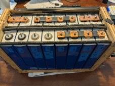
Hello, I pulled my DIY battery pack out of the truck and am performing a more thorough inspection and maintenance. I has been installed in an off-road vehicle for two years, and while I try to be as gentle as possible, it has seen some bumps and vibrations from typically off-road driving (primarily washboard roads in and around Death Valley). The pack consists of 8x of the EVE 105Ah cells in a 2P4S configuration (210Ah). It is securely mounted to the vehicle and in a compression rig.

What drove this exercise is a lower than expected capacity test of ~190Ah. The cell pairs stay fairly balanced through the full charge/discharge curve, but cell pairs 1 and 3 deviate quite a bit at the lower and upper end as shown, limiting the capacity. I am hoping a fresh top balance will help with this (cells were top balanced initially two years ago).

Would like to get some thoughts and opinions on the overall condition and health of the system.

Capacity testing:

Middle of charge showing cells fairly balanced:
1662410269930.png

Cell HVD 3.6V (end of charge):
1662410087521.png

Cell LVD 2.8V (end of discharge):
1662410112519.png


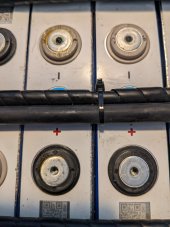
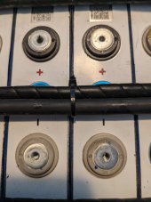
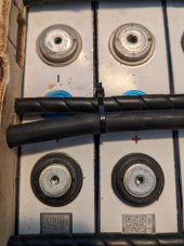
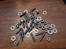
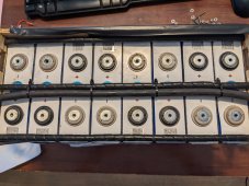
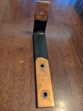
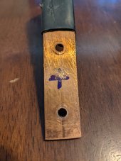
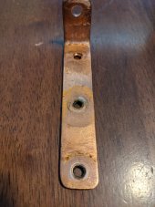
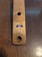
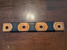
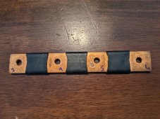
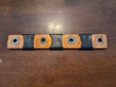
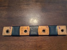
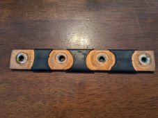
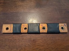
I pulled the busbars and inspected everything. I also measured the internal resistance of each cell using this technique

1662410767530.png
 

Attachments

  • PXL_20220905_174332513.jpg
    PXL_20220905_174332513.jpg
    256.6 KB · Views: 10
Last edited:
Pulled the busbars off to inspect and ultimately do a top balance. I did notice significant oxidation on the bottom of the busbar connecting cells 5-8, and some on busbar connecting cells 1-4. The middle busbar connecting cells 3-6 looked pretty good. I used Permatex threadlocker purple on the studs, and NOALOX between the busbar and cell terminals.

Cell pairs 1, 2, 3, 4 and stainless hardware.
 

Attachments

  • PXL_20220905_175619021.jpg
    PXL_20220905_175619021.jpg
    146.7 KB · Views: 10
  • PXL_20220905_175614868.jpg
    PXL_20220905_175614868.jpg
    136.6 KB · Views: 11
  • PXL_20220905_175611444.MP.jpg
    PXL_20220905_175611444.MP.jpg
    127.1 KB · Views: 9
  • PXL_20220905_175607735.jpg
    PXL_20220905_175607735.jpg
    131.5 KB · Views: 9
  • PXL_20220905_175640643.jpg
    PXL_20220905_175640643.jpg
    360.1 KB · Views: 9
  • PXL_20220905_175556063.jpg
    PXL_20220905_175556063.jpg
    283.3 KB · Views: 9
Last edited:
Busbars
 

Attachments

  • PXL_20220905_175709468.MP.jpg
    PXL_20220905_175709468.MP.jpg
    149 KB · Views: 7
  • PXL_20220905_175719674.jpg
    PXL_20220905_175719674.jpg
    135.6 KB · Views: 9
  • PXL_20220905_175730295.jpg
    PXL_20220905_175730295.jpg
    140.1 KB · Views: 10
  • PXL_20220905_175736556.jpg
    PXL_20220905_175736556.jpg
    119.2 KB · Views: 9
  • PXL_20220905_175751292.jpg
    PXL_20220905_175751292.jpg
    312.4 KB · Views: 8
  • PXL_20220905_175756519.jpg
    PXL_20220905_175756519.jpg
    309.4 KB · Views: 9
  • PXL_20220905_175806809.jpg
    PXL_20220905_175806809.jpg
    295.3 KB · Views: 9
  • PXL_20220905_175812937.jpg
    PXL_20220905_175812937.jpg
    303.9 KB · Views: 7
  • PXL_20220905_175823138.jpg
    PXL_20220905_175823138.jpg
    318.2 KB · Views: 5
  • PXL_20220905_175828257.jpg
    PXL_20220905_175828257.jpg
    285.5 KB · Views: 7
Any comments are appreciated. Mainly how does the pack look after a couple of years in moderately rough service? Should I do anything differently? I may skip the threadlocker this time.

Any way to prevent the oxidation? That may be causing an increased resistance and contributing to the lower capacity.

Thank you.
 
Last edited:
Definitely needs rebalancing (consider getting an active balancer?) and you might want to use tined busbars to minimize that corrosion. Liquid tin could also be applied to your existing copper busbars.
 
Was the torque to undo the fasteners about the same? Or were the ones with corrosion a bit off?
 
>200mV delta V @ 13.8V and cell 2 about to run away, suggests significantly out of balance pack. This is why pack capacity has dropped. Could be either B cell quality or connection issues. Checking for voltage drop across adjacent terminals connected with busbars with high current flowing thru pack or thermal gun is one way of checking for possible connection problems. If it is cell quality then will definitely need an active balancer long term if you are going to get any further reasonable life out of pack. This is the JK BMS 4S 2A version JK-B2A8S20P
 
Was the torque to undo the fasteners about the same? Or were the ones with corrosion a bit off?

About the same. These are M4 studs so I don't put too much torque on them. I screw in the studs by hand until they bottom out, then back off slightly. Then I hold the stud from turning using a hex key while I tighten the nylock nut with an open end wrench. I don't use a torque wrench, but rather torque the nut by "feel".

Perhaps the corrosion could be from an inconsistent application of the threadlocker?
 
>200mV delta V @ 13.8V and cell 2 about to run away, suggests significantly out of balance pack. This is why pack capacity has dropped. Could be either B cell quality or connection issues. Checking for voltage drop across adjacent terminals connected with busbars with high current flowing thru pack or thermal gun is one way of checking for possible connection problems. If it is cell quality then will definitely need an active balancer long term if you are going to get any further reasonable life out of pack. This is the JK BMS 4S 2A version JK-B2A8S20P

I figure out of balance at the least. Cells were new and matched and hopefully still in good shape. I am top balancing the cells now and once I put them back in a 2P4S pack will run another capacity test.

I will measure for voltage drop during a large load like you mention as well.
 
I figure out of balance at the least. Cells were new and matched and hopefully still in good shape. I am top balancing the cells now and once I put them back in a 2P4S pack will run another capacity test.

I will measure for voltage drop during a large load like you mention as well.
A cheap option to consider if you want better balancing power is the 4S 5A capacitor type - https://www.aliexpress.com/item/4001221243997.html
Some have good success with these as an add-on and as you have an open pack and already have a BMS with bluetooth cell voltage monitoring, just disable the BMS passive balancing and hook one up. This active balancer is said to push approx 1A @100mA and 2A@200mV delta V (so 5A in specs is an over statement). The balancer pcb has two contacts that you can use to add a switch that you can use to switch balancing on and off. So you can "top balance" insitu as needed by floating at 14.0V with a controlled charger until delta V drops to 10-15mV. Will take a long time with delta V of 200mV (days to weeks) but will get there.

From your figures above it looks as though your pack BMS may have needed to disconnect the pack as approaching 14.0V because of that run away cell when you had the pack in your vehicle. Most DC DC chargers push LiFePO4 past 14.0V

Thanks I'll check it out. I prefer not to use active balancing at all. I am hoping the initial top balance wasn't done completely/correctly and a fresh top balance will make things right.

I don't want the BMS to terminate charging, I configure the charger to stop before the BMS hits the HVD.
 
In a 2P system (two cells in parallel) it's critically important that your busbars make perfect electrical contact with the cells. Oxidation kills that. This is probably why you went out of balance (because in a 2P system it's very easy to get different charge rates into the paralleled cells ... unlike 1P systems). There are threads here you can search for for oxidation and items like noalox to prevent oxidation as well as methods to clean the busbars and terminals just before assembling.
 
In a 2P system (two cells in parallel) it's critically important that your busbars make perfect electrical contact with the cells. Oxidation kills that. This is probably why you went out of balance (because in a 2P system it's very easy to get different charge rates into the paralleled cells ... unlike 1P systems). There are threads here you can search for for oxidation and items like noalox to prevent oxidation as well as methods to clean the busbars and terminals just before assembling.
Agreed, but even if these steps are taken, oxidation will still build over time creating a delta... Which is why I don't care for the idea of doing 2P.
 
I top balanced the cells again to 3.60V then reassembled. I used noalox again, but didn't use the threadlocker this time. Got just over 204Ah. Still not 210Ah, but I think this is acceptable.

Cell voltage difference was around 12mV from fully charged down to about 12.68V, then started to deviate more. I did notice that the BMS reported cell voltage difference didn't exactly match my DMM. According to the DMM, the difference was around 15mV when the BMS was reporting over 20mV.

1663090526296.png

1663090554883.png
 
Last edited:
In a 2P system (two cells in parallel) it's critically important that your busbars make perfect electrical contact with the cells. Oxidation kills that. This is probably why you went out of balance (because in a 2P system it's very easy to get different charge rates into the paralleled cells ... unlike 1P systems). There are threads here you can search for for oxidation and items like noalox to prevent oxidation as well as methods to clean the busbars and terminals just before assembling.

I think this is the main issue. I really don't care for the 2P4S configuration, but that was the only way I could get the capacity using cells that fit my space. I have been considering going to a 4S configuration, which would give me 100Ah. I probably don't really need 200Ah...
 
About the same. These are M4 studs so I don't put too much torque on them. I screw in the studs by hand until they bottom out, then back off slightly. Then I hold the stud from turning using a hex key while I tighten the nylock nut with an open end wrench. I don't use a torque wrench, but rather torque the nut by "feel".

Perhaps the corrosion could be from an inconsistent application of the threadlocker?
Or an inconsistent application of the "torque" wrench
 
Float your pack at 14.0 -14.2 V and allow your passive balancer to fine tune. Hopefully you can get deltaV towards 10mV with no runaway cells.
 
Float your pack at 14.0 -14.2 V and allow your passive balancer to fine tune. Hopefully you can get deltaV towards 10mV with no runaway cells.

I am planning on setting the charger float to 14.0V, and the BMS HVD to 3.6V/14.4V.

Active balancing doesn't really work well with my usage. Not enough time at higher voltages. This is installed in a recreation vehicle that is parked in the garage most of the time. I keep the pack around half charged when not in use. Before a trip I will charge it fully using a bench charger, then will maintain charge on the road with a 18A Victron Orion DC/DC.

Voltage difference seems to be holding around 12-15mV from 15% to close to 100%. Below 15%, cell pair 1 primarily, and cell pair 2 somewhat, start to runaway. I am charging now and will check the voltage difference on the top end.
 
Back
Top