diy solar

diy solar

How is inverter bus capacitance chosen?

Roswell Bob

Solar Enthusiast
Joined
Dec 5, 2020
Messages
759
Location
Warner, NH
Does anyone know how the bus capacitance of an inverter is chosen? I have been told that a 6kW inverter should have 0.1F from one source, and 0.028F from another source.
 
Does anyone know how the bus capacitance of an inverter is chosen? I have been told that a 6kW inverter should have 0.1F from one source, and 0.028F from another source.

I would be surprised if there is a single rule or guideline for this. It is going to vary significantly with the type of inverter (low vs high frequency), the design of the rest of the circuit, the design objectives of the inverter, and the quality of the inverter. It is probably safe to assume that high-quality, low-frequency, pure sine wave inverters are going to have a lot more capacitance on the front end than a low-quality, high-frequency modified sine wave cheapy inverter of the same rating. I would be hard-pressed to be any more specific than that.

Even if you limit the question to similar inverters (e.g. Pure sign wave, low frequency, 6KW inverters) there is likely to be a pretty large variance from one manufacturer to the next.

I know this does not answer the question, but there are just too many variables to be able to provide any type of guidance. Furthermore, since this information is not published by the manufacturers, it is hard to even know what the typical range would be.
 
If by bus capacitance you are referring to battery DC input to inverter, the purpose is to supply the high frequency PWM pulse peak MOSFET switching currents. Battery DC input PWM rate runs from about 6 kHz to over 25 kHz. Low freq inverter, heavy transformers generally use lower PWM freq, while high frequency inverters run higher PWM switching freq. Below 15-20 KHz there is possibility of audible noise emitted as this is within human hearing range.

It is not only the capacitance that is important but also the ESR (effective series resistance) of the capacitors. Also, parasitic circuit inductance is important.

Peak high frequency pulse current can be 4 to 6 times the average DC battery current. Even at high frequency this still takes a respectable amount of capacitance to supply the peak high frequency current pulse of hundreds of amps over the period of the high freq pulse. You typically find three or four 5,000 to 10,000 uFd electrolytic caps in parallel for these input capacitors on inverter PCB.

Insufficient or degraded input capacitance causes large voltage ringing spikes in conjunction with series inductance of battery cables. The voltage ringing can damage components in inverter, particularly switching MOSFET's due to exceeding their breakdown voltage rating. It is advisable that positive and negative battery cables are taped together. This reduces battery cable series inductance by better than half the value thereby reducing voltage ringing on inverter input compared to pos and neg cables run with 6-12 inches of separation. Taping pos-neg battery cables together also helps to cancel their nearby magnetic fields that can cause 120 Hz buzz in nearby metal objects, like a metal breaker box.

Contrary to common mis-perception, these input capacitors do very little to nothing to reduce the large 120 Hz ripple current on battery lines for a sinewave inverter. That would take many Farads of capacitance in accordance with I = C * delta V / delta time, where time is the gap between 120 Hz peaks. The peak 120 Hz ripple current is a bit greater than twice the average DC battery current and can be greater for poor AC power factor loads like inductive AC motors.

There is another somewhat mis-perception on making initial battery input connection to inverter which results in high surge current to charge these caps to battery voltage. Any reasonable quality cap is capable of taking this surge current with all the series resistance in battery, BMS, battery cables, and inverter PCB connections. Some cheap BMS's may trip for overcurrent although most have sequencing of the parallel current pass MOSFET's to limit startup surge current or an additional separate MOSFET with series power resistor to limit initial surge current.. The most damaging effect is that of pitting expensive high current DC breaker contacts which over multiple make/breaks increases the breaker resistance so breaker gets hot during high load current and potentially burning up.
 
Last edited:
RCinFLA has said it pretty well and touched on the battery cable L-C resonance issue which is a very real issue, especially in the large 60 Hz transformer inverters.

I would add capacitance if the electrolytics are heating up more than you would like due to ESR. They say that for every 10 degrees C rise, the capacitor's life is shortened by two. At least caps don't seem to dry out the way they did 50+ years ago.

Also, high frequency inverters, that store energy on their high voltage link rails, tend to have less 120 Hz battery side ripple so that can help their battery side ripple that can cause the battery cable L-C resonance issues and high voltage peaks on their low voltage input stages.
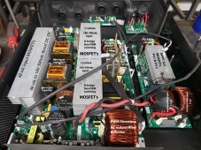
You can also add a slight amount of external capacitor resistance if you want to make sure the filtering and ringing was critically damped but that might be a nightmare to get right for various batter cable lengths. That was something we entertained back at Trace Engineering.

So, extra capacitance is great if the existing caps are getting hot and there is available room for them and can reduce heat.

boB
 
Also, high frequency inverters, that store energy on their high voltage link rails, tend to have less 120 Hz battery side ripple so that can help their battery side ripple that can cause the battery cable L-C resonance issues and high voltage peaks on their low voltage input stages.
I am not a fan of HF hybrid inverters, but you got me curious on how much help the HV DC filter cap will do.

I know the LV6548 split phase 240/120v HF inverter has 1500 uF with 315 vdc rated HV filter caps for each of the 120vac inverter sections. I will have to do the simulation to see how much a 1500 uF cap at say 275 vdc will help for 120 Hz ripple. My initial gut says not too much at 3kW 120vac output with 25 amps rms AC output current. I think 1500 uF will just about get rid of HF switching at 3kW load.

LV6548 Pict breakdown.png
 
Last edited:
I thought that looked like an MPP inverter !

Looks like they have possibly reduced the complexity a bit but it is kind of hard to tell.

Does they still use a separate charger from the inverter to go from HV to 48V ?

Are you sure that the inverter sinewave PWM section is MOSFETs and not IGBTs ? I think that's what they used to use but the one I looked at was from like, 5 years ago and was 230VAC 50Hz only.

The HV capacitors help reduce 48V ripple but maybe only about 1/3rd or so of what it would be at those microfarads. Any reduction is better than nothing. You should see the DC battery current drop to some non-zero current at zero-crossing.

boB
 
Last edited:
I thought that looked like an MPP inverter !

Looks like they have possibly reduced the complexity a bit but it is kind of hard to tell.

Does they still use a separate charger from the inverter to go from HV to 48V ?

Are you sure that the inverter sinewave PWM section is MOSFETs and not IGBTs ? I think that's what they used to use but the one I looked at was from like, 5 years ago and was 230VAC 50Hz only.

The HV capacitors help reduce 48V ripple but maybe only about 1/3rd or so of what it would be at those microfarads. Any reduction is better than nothing.

boB
Yes, the HV output sinewave PWM devices maybe IGBT's. Same thing, only different ;)

HF 240/120 vac inverters are essentially two 120 vac HF inverters in series. Two things that threw me initially was the two wires from PV SCC to HV filter caps and the common single PWM sinewave output filter torroid.

Turns out the two DC to HV DC converters are rigged so the two 1500 uF caps are in series with the PV feeds two wires across the two series caps at twice the voltage of each split phase HV DC converter. They are injecting PV power to HV DC filter caps. Charging from PV has added loss of HV DC to Batt DC first stage converter but any PV to AC push doesn't go through DC-HV DC converter.

With the common center connection on HV filter caps they must run the output PWM IGBT's out of phase which also allows the output filter torroid to run like a common mode choke, although the filtering is not common mode, just 180 degs out of phase AC input. Just cuts down their cost of two filter torroids separately on each split phase.

This picture was posted by another OP earlier because it failed. Likely the common HF inverter issue of batt input MOSFET's blown out due to DC to HV DC converter excessive MOSFET current caused by HF ferrite transformer overload saturation. (why I am not a fan of HF hybrid inverters)
 
I am curious: Why do you ask?
I have done motor drives where the primary concern is ripple current - a good portion of the ripple current is from the input side. Capacitors were for the most part chosen to deal with the ripple current. How long would they last was our main concern. The actual capacitance was not so important-we bought caps for ripple current capability. Over the years capacitor technology improved with higher ripple ratings per volume.

These 60Hz inverters running off of solid dc have to deal with mainly load side currents. Currents at the fundamental and carrier frequencies. I am thinking the bus could move around quite a bit so that capacitance may be the driving factor. Small unloaded motors act like an inductor and might be worse case. Small motors can actually have more reactive current at no load than full load current. It is a bit strange to load up a small motor on a dyno and watch the current go down.

Low frequency inverters would need quite a bit of current capacity as the current is very high at the lower switching voltages. The HF inverter would need higher voltage rating on the caps so costwise it is probably a wash, but may have an advantage in that the bus voltage could be stabilized with a relatively slow loop. (If keeping the bus stable offers any advantage.) The trade with a HF inverter is then a few lines of code for a savings in bus cap cost.
 
If by bus capacitance you are referring to battery DC input to inverter, the purpose is to supply the high frequency PWM pulse peak MOSFET switching currents. Battery DC input PWM rate runs from about 6 kHz to over 25 kHz. Low freq inverter, heavy transformers generally use lower PWM freq, while high frequency inverters run higher PWM switching freq. Below 15-20 KHz there is possibility of audible noise emitted as this is within human hearing range.

It is not only the capacitance that is important but also the ESR (effective series resistance) of the capacitors. Also, parasitic circuit inductance is important.

Peak high frequency pulse current can be 4 to 6 times the average DC battery current. Even at high frequency this still takes a respectable amount of capacitance to supply the peak high frequency current pulse of hundreds of amps over the period of the high freq pulse. You typically find three or four 5,000 to 10,000 uFd electrolytic caps in parallel for these input capacitors on inverter PCB.

Insufficient or degraded input capacitance causes large voltage ringing spikes in conjunction with series inductance of battery cables. The voltage ringing can damage components in inverter, particularly switching MOSFET's due to exceeding their breakdown voltage rating. It is advisable that positive and negative battery cables are taped together. This reduces battery cable series inductance by better than half the value thereby reducing voltage ringing on inverter input compared to pos and neg cables run with 6-12 inches of separation. Taping pos-neg battery cables together also helps to cancel their nearby magnetic fields that can cause 120 Hz buzz in nearby metal objects, like a metal breaker box.

Contrary to common mis-perception, these input capacitors do very little to nothing to reduce the large 120 Hz ripple current on battery lines for a sinewave inverter. That would take many Farads of capacitance in accordance with I = C * delta V / delta time, where time is the gap between 120 Hz peaks. The peak 120 Hz ripple current is a bit greater than twice the average DC battery current and can be greater for poor AC power factor loads like inductive AC motors.

There is another somewhat mis-perception on making initial battery input connection to inverter which results in high surge current to charge these caps to battery voltage. Any reasonable quality cap is capable of taking this surge current with all the series resistance in battery, BMS, battery cables, and inverter PCB connections. Some cheap BMS's may trip for overcurrent although most have sequencing of the parallel current pass MOSFET's to limit startup surge current or an additional separate MOSFET with series power resistor to limit initial surge current.. The most damaging effect is that of pitting expensive high current DC breaker contacts which over multiple make/breaks increases the breaker resistance so breaker gets hot during high load current and potentially burning up.
Yes low inductance bus structures are very important. DRC snubbers do a nice job taking care of the ringing. Maybe best approach is to mount switches directly on top of cells. A filter inductor between cell array and inverter bus might be a good strategy if the intent is to get rid of any 60Hz. I did quick simulation of 7.5HP unloaded motor on .028F bus and saw about 4v pk-pk on the caps. Not bad. I will look at current into the cells. Yes, electrolytic caps can take pretty much whatever you can throw at them- no prob. Yes, a single mosfet can charge a very large bus without a resistor if it is turned on in a particular manner. I wonder what the BMS I a putting into my system is using for start-up. Good points - thanks.
 
Yes, a single mosfet can charge a very large bus without a resistor if it is turned on in a particular manner. I wonder what the BMS I a putting into my system is using for start-up. Good points - thanks.
This is related to a point that is often discussed on this forum. A lot of people are concerned that when a BMS first turns on, the surge current will be a problem that could either cause the BMS to think there is a short and turn back off or, worse, damage something. However, I don't see this in real life.....and I don't hear reports of this actually happening on the forum.
 
This is related to a point that is often discussed on this forum. A lot of people are concerned that when a BMS first turns on, the surge current will be a problem that could either cause the BMS to think there is a short and turn back off or, worse, damage something. However, I don't see this in real life.....and I don't hear reports of this actually happening on the forum.

Good news. I threw this around last week and you replied. I'm going to omit the precharge circuit unless I find out I need it. I decided on a 200A Class T. It should be able to get the bus up to 60v without getting close to the melting I^2t. I picked out a beaker with a type D curve that likewise should not be bothered by inrush.
 
Good news. I threw this around last week and you replied. I'm going to omit the precharge circuit unless I find out I need it. I decided on a 200A Class T. It should be able to get the bus up to 60v without getting close to the melting I^2t. I picked out a beaker with a type D curve that likewise should not be bothered by inrush.

That may depend on how much capacitance your inverters have, and battery internal resistance.


BTW: If the BMS is already turned on and then suddenly hooked to the inverter, it CAN make the BMS think there is a short. I have seen that happen and in some of Will's early videos, he experienced it. However, this is different than when the BMS turns on while hooked to the inverter.
 
That may depend on how much capacitance your inverters have, and battery internal resistance.


Yes, I would still do a pre-charge circuit on any inverter disconnect switch...... but that appears to be a different case than when the BMS is turning on and off. From experience, it appears that when the BMS turns on, the FET current ramps slow enough to avoid problems. Whether this is a happy coincidence or by design, I don't know.
 
I am curious: Why do you ask?
I was just thinking there really isn't a rule of thumb or a clear cut formula . When running 3 phase motor drives off of grid there is quite a bit of 360Hz ripple. If there is line imbalance we see 120Hz as well. Both the fundamental output frequencies and the carrier rates each produce another set of bus currents. With (60Hz) inverter running off batteries there will be a 120Hz component. I expect these 120Hz products might best be dealt with electrolytics, while film /ceramic might be best for the higher frequency currents produced at the carrier rates.
 
My scope measurements of battery ripple show a substantial portion of the 60 Hz current comes from battery. I only ran the inverter at 40% load, but think if it was 100% load nearly all ripple current would come from the batteries. Battery is pretty "stiff", so not much voltage ripple allowed, therefore not much power supplied by caps.

I think even the electrolytics mostly supply higher switching frequencies to a LF inverter.
For a typical HF inverter, the electrolytics would probably supply the 60 Hz, but with much higher voltage ripple.
 
The input capacitor's ESR (internal series resistance) rating is a significant factor in their self-heating due to ripple current. This effects their lifetime. Heating accelerates drying out their electrolyte. As electrolyte dries out their capacitance drops. As input capacitors drop in value there is more voltage ringing spikes on input switching MOSFET. When voltage spikes get too great it can blow out the MOSFET's.

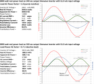
The battery current is the green graph. It is 120 Hz for 60Hz inverter. Poor load power factor makes peak currents increase which also increases inverter losses.

The large 120 Hz current causes strong magnetic fields around battery lines which can cause 120 Hz buzzing to any nearby metal objects like a loose-fitting metal breaker box lid. Keeping pos-neg lines taped together helps to cancel their magnetic fields and reduces battery line series inductance that causes voltage ringing on inverter DC input further stressing the input capacitors.

These graphs have 60 watts constant inverter overhead load current but is lost in the noise compared to the 3kW load example.

Inverter power factor waveform.png
 
My scope measurements of battery ripple show a substantial portion of the 60 Hz current comes from battery. I only ran the inverter at 40% load, but think if it was 100% load nearly all ripple current would come from the batteries. Battery is pretty "stiff", so not much voltage ripple allowed, therefore not much power supplied by caps.

I think even the electrolytics mostly supply higher switching frequencies to a LF inverter.
For a typical HF inverter, the electrolytics would probably supply the 60 Hz, but with much higher voltage ripple.
I would want the high frequency taken care of at the bus structure.. It never gets a chance to travel down the battery cables. i think covering the available area with a mix of different technologies would be best. I like ceramic right there. I suppose the best design would put a lithium battery pack very close to the bus. Some kind of current sensor between them. Yea, battery is good for supplying ripple current - a lot like a capacitor :)
 
Back
Top