diy solar

diy solar

How many 1/0 to get proper binding in a 4/0 lug?

DerpsyDoodler

Solar Addict
Joined
Jan 10, 2021
Messages
2,247
I need to join my 2 battery negatives (1/0 each) into a single 4/0 butt splice to 4/0 wire. i am joining these to run them through the shunt.

I could just put a 1/0 lug on the end of each battery begative, then double the 2 lugs on the shunt stud, but my concern is this may cause resistance imbalance in the circuit leading to one battery being used/stressed more than the other.

Is the concern negligible in this case?

Should I splice to 4/0 or just double up 1/0 lugs on the shunt?
You would do better with a busbar, connect the 1/0 lugs to the busbar, then your cable with 4/0 to the busbar. Install the shunt after the busbar. Doubling cables on a single lug is not preferred as resistance between layers causing balance issues plus under high load heating of the connection.

The 1/0 cables should be equal length when in parallel, both negative and positive. This helps prevent imbalance.
 
I need to join my 2 battery negatives (1/0 each) into a single 4/0 butt splice to 4/0 wire. i am joining these to run them through the shunt.

I could just put a 1/0 lug on the end of each battery begative, then double the 2 lugs on the shunt stud, but my concern is this may cause resistance imbalance in the circuit leading to one battery being used/stressed more than the other.

Is the concern negligible in this case?

Should I splice to 4/0 or just double up 1/0 lugs on the shunt?

If you did stack two lugs on one stud of shunt (on negative side), then stacking lugs in the opposite direction on stud of fuse (positive side) should exactly match resistance.

Some terminals have a screw which bears on the wire. Others have non-rotating surfaces to clamp the wire. Although NEC doesn't allow two wires in a terminal (except if parts listed for that, e.g. split bolts) it is difficult to see how it would cause a problem for some configurations. But some with screw directly on wire can miss a small gauge solid wire.

One thing I've done is to use a lug to hold one wire and splice a second one to it with split bolt. Within ampacity limits, of course. I didn't need matched resistance in that case.

I have stripped the middle of a wire and fed it through a screw-terminal lug, to connect two loads. (Most lugs have screw in the way and wouldn't allow this, but the lug in a fused disconnect had clearance.) Some battery cable lugs go in the middle, or have two crimps.


You would do better with a busbar, connect the 1/0 lugs to the busbar, then your cable with 4/0 to the busbar. Install the shunt after the busbar. Doubling cables on a single lug is not preferred as resistance between layers causing balance issues plus under high load heating of the connection.

The 1/0 cables should be equal length when in parallel, both negative and positive. This helps prevent imbalance.

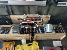
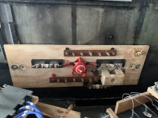
Thanks for your response. Ive attached a picture. I am using bus bars. I still need only the battery negative to pass through the shunt. The bus bars will have mppt controllers connected, also. not breaking out a second set of bus bars just for the batteries. the only load to be connected to these (other than shunt and precharge) will be the inverter. if i need dc circuitry to power loads, i may just do so with a converter plugged into my ac/dc distro panel. while id be losing power inverting then converting, i don’t want to have to install another fuse, then another 10ft cable run to the distro panel that will be mounted underneath the coach. I’m not planning on any DC loads, and if i encounter a DC load i want, I will toy with other solutions unless or until my DC needs justify a new fused run or conceeding to the inversion conversion loss of installing a converter powered by the inverter at the distro panel. or maybe even only wiring the converter to the second 50a leg so only available on 50a shore power.

top right is shunt, top left negative bus bar, bottom left positive bus bar. the rest of the components are fuses, precharge circuit, and disconnect.

AFA6089D-940A-48EB-AFF5-D8E7024A816A.jpeg
 
If you did stack two lugs on one stud of shunt (on negative side), then stacking lugs in the opposite direction on stud of fuse (positive side) should exactly match resistance.

Some terminals have a screw which bears on the wire. Others have non-rotating surfaces to clamp the wire. Although NEC doesn't allow two wires in a terminal (except if parts listed for that, e.g. split bolts) it is difficult to see how it would cause a problem for some configurations. But some with screw directly on wire can miss a small gauge solid wire.

One thing I've done is to use a lug to hold one wire and splice a second one to it with split bolt. Within ampacity limits, of course. I didn't need matched resistance in that case.

I have stripped the middle of a wire and fed it through a screw-terminal lug, to connect two loads. (Most lugs have screw in the way and wouldn't allow this, but the lug in a fused disconnect had clearance.) Some battery cable lugs go in the middle, or have two crimps.


Thanks for your response, Hedges. I thought anout “reversing the connection”, but wasn’t entirely certain.

with that said, if battery 1 positive was closest to load on positive bar, it should be furthest from load on negative bar. This means that ensuring doubling the lugs on the shunt with battery 2 negative “closest” to the bus bar (therefore first lug on the stud) should suffice.

Is that correct? I hope I didnt make that more confusing than it needs to be.
 
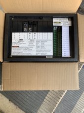
here’s a better picture of the distribution disconnect panel.

EE6D2226-03C6-40C6-9FFA-83851E120FA5.jpeg

edit: didnt want to use the term “distribution panel“ in an ambiguous way. i have an ac/dc distribution panel with circuit breakers and fused dc circuitry that will live in the underbelly.

edit: added pic of distribution panel
 

Attachments

  • 88C8365F-6A84-4203-A7C8-40BE57AEA2BC.jpeg
    88C8365F-6A84-4203-A7C8-40BE57AEA2BC.jpeg
    188 KB · Views: 8
Last edited:
I need to join my 2 battery negatives (1/0 each) into a single 4/0 butt splice to 4/0 wire. i am joining these to run them through the shunt.

Alternatively, daisy chain the two batteries:
Battery A (-) to Battery B (-) to shunt
Fuse B to Fuse A to switch

Using same length/gauge wire between two battery (-) as between two fuse provide the balancing (all other connections within battery and BMS have to be matched as well.)

Doing this, you don't get independent battery switching. Of course, connecting just one battery means making SoC imbalanced.
The way your switch is shown, it appears it has two SPST contacts, not two batteries connecting to one terminal. In this case, you can heave each fuse also wire separately to the switch. Daisy chain output of switch B to switch A with a longer cable matching daisy chain of battery (-). Then wire from switch A to load.

Thanks for your response, Hedges. I thought anout “reversing the connection”, but wasn’t entirely certain.

with that said, if battery 1 positive was closest to load on positive bar, it should be furthest from load on negative bar. This means that ensuring doubling the lugs on the shunt with battery 2 negative “closest” to the bus bar (therefore first lug on the stud) should suffice.

Is that correct? I hope I didnt make that more confusing than it needs to be.

Yes, closest on one, furthest on other.

Stacking a pair of lugs on shunt seems easiest. Then, if resistance difference from stacking is thought to matter, you would stack the two cables from switch onto a single stud of busbar.

All this wood ... at least, no metal contacts that might get hot are in contact with wood; they have a plastic insulator first.
Got an IR thermometer? Would be good to check temperatures at high current (after a while.) Checking voltage drops would give early indication.
I was looking up clamp ammeters. FLIR has one which includes an IR camera. Rather expensive, low resolution image, and most important didn't do DC amps (only AC.)
 
In my experience (NEC notwithstanding), slightly different resistances in multiple cables still works just fine, as long as they are over-cabled and close.

I use four 10awg 200c silicone wires to carry 150 amps (surge) on my battery. They are configured as two wires per 8awg lug. At full draw (150a) each wire has between 35-40a amps per conductor, which is still well within wire spec. The big thing is to test then with an amp-clamp to make SURE each wire is getting somewhat even current, and that your crimps are good.

I'm sure it's not "best practice" to do that, but it works for me, and running a large wire in a very tight space just wasn't an option.
 
Alternatively, daisy chain the two batteries:
Battery A (-) to Battery B (-) to shunt
Fuse B to Fuse A to switch

Using same length/gauge wire between two battery (-) as between two fuse provide the balancing (all other connections within battery and BMS have to be matched as well.)

Doing this, you don't get independent battery switching. Of course, connecting just one battery means making SoC imbalanced.
The way your switch is shown, it appears it has two SPST contacts, not two batteries connecting to one terminal. In this case, you can heave each fuse also wire separately to the switch. Daisy chain output of switch B to switch A with a longer cable matching daisy chain of battery (-). Then wire from switch A to load.


Yes, closest on one, furthest on other.

Stacking a pair of lugs on shunt seems easiest.
my thoughts exactly.
Then, if resistance difference from stacking is thought to matter, you would stack the two cables from switch onto a single stud of busbar.
i don‘t forsee that as a problem. Do you?
All this wood ... at least, no metal contacts that might get hot are in contact with wood; they have a plastic insulator first.
correct
Got an IR thermometer? Would be good to check temperatures at high current (after a while.) Checking voltage drops would give early indication.
I was looking up clamp ammeters. FLIR has one which includes an IR camera. Rather expensive, low resolution image, and most important didn't do DC amps (only AC.)
i do not have a thermal/ir camera, yet. i plan to invest in one. i do have a klein clamp ameter.

i will be checking all of this. I don’t plan on installing, lidding it, and forgetting about it, at least not until i have confidence in all of the crimps/connections.
 
In my experience (NEC notwithstanding), slightly different resistances in multiple cables still works just fine, as long as they are over-cabled and close.

I use four 10awg 200c silicone wires to carry 150 amps (surge) on my battery. They are configured as two wires per 8awg lug. At full draw (150a) each wire has between 35-40a amps per conductor, which is still well within wire spec. The big thing is to test then with an amp-clamp to make SURE each wire is getting somewhat even current, and that your crimps are good.

I'm sure it's not "best practice" to do that, but it works for me, and running a large wire in a very tight space just wasn't an option.
Thanks! Good advice. luckily i don’t have tight space problems. i am able to use the wire sizes needed. I just have to make sure i’m able to properly meter my batteries.

i’m using butt connectors to join the 6 wires off the BMS to 0 cable. not best practice, but it works fine. i used a smaller than 0 crimp on the side with the 6x10awg wires to make sure i got a good crimp. it created wings on the lug, but i filed them down and covered with heat shrink.
 
Alternatively, daisy chain the two batteries:
Battery A (-) to Battery B (-) to shunt
Fuse B to Fuse A to switch

Using same length/gauge wire between two battery (-) as between two fuse provide the balancing (all other connections within battery and BMS have to be matched as well.)

Doing this, you don't get independent battery switching. Of course, connecting just one battery means making SoC imbalanced.
The way your switch is shown, it appears it has two SPST contacts, not two batteries connecting to one terminal. In this case, you can heave each fuse also wire separately to the switch. Daisy chain output of switch B to switch A with a longer cable matching daisy chain of battery (-). Then wire from switch A to load.


Yes, closest on one, furthest on other.

Stacking a pair of lugs on shunt seems easiest. Then, if resistance difference from stacking is thought to matter, you would stack the two cables from switch onto a single stud of busbar.

All this wood ... at least, no metal contacts that might get hot are in contact with wood; they have a plastic insulator first.
Got an IR thermometer? Would be good to check temperatures at high current (after a while.) Checking voltage drops would give early indication.
I was looking up clamp ammeters. FLIR has one which includes an IR camera. Rather expensive, low resolution image, and most important didn't do DC amps (only AC.)

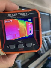
Purchased my thermal camera:

image.jpg
 
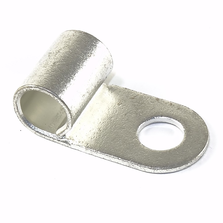
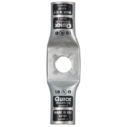
Grainger_6510FxxConnectorsxxLugxxMagnaLugxxLocking%20Anti%20Rotating%20StackablexxDual.png


https://www.zoro.com/quickcable-magnalug-dual-wire-10-pk5
 
Back
Top