diy solar

diy solar

How to combine AC in and outs of multiple inverter/charge controllers?

"200A sub-panel will have a 150A main breaker, and the back feeding breakers are 2 double pole 70A"

When you say "backfeed" it makes me think of PV breakers in a panel fed by grid with 200A. 200A x 120% = 240A, 240A - 150A = 90A so only a single 70A PV breaker would have been allowed.

But for your off-grid system, the only source feeding the panel is the two 70A breakers? Or do you have AC coupled PV as well as battery inverter? I think 4x EG4 is the only AC source I see in the drawing. So I don't think 120% rule applies.

What is the 150A breaker for? Just switching off power through 2/0 cables to main panel, which has 200A breaker?
I don't think you'll ever hit 150A, much less 200A. I think 200A breaker could be used in either/both panels. Same goes for 150A breaker.

By the way, there are some 225A busbar panels. Maybe only in QO series, not homeline.

Neutral ground bond seems like it's in the right place now. From there, wires to ground rod(s), gas and water pipes, foundation steel if available.

When you say "backfeed"...
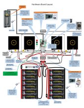
No I am referring to AC coming in from the inverters to the sub-panel. There is NO grid, this is in the middle of nowhere, no power, no water, no sewer, and internet is coming from Starlink. Because there are 4 inverters = 2 in parallel for L1, 2 in parallel for L2, and how I am combining them is using this sub-panel and 70A breakers, you've got two red wires from the left side inverters (L1), and two black wires from the right side inverters (L2), totally 4 wires to feed into the two double pole 70A breakers.
But for your off-grid system, the only source feeding the panel is the two 70A breakers?...
Correct. The only AC feeding the sub-panel is the AC Out from each of the inverters. The inverters, however, are connected to the battery bank, and the solar arrays.
Neutral ground bond seems like it's in the right place now. From there,...
So I think what you're saying is I need to move the grounding wire going to the grounding rods from the Main Panel to the sub-panel?
 
I think ground wire to ground rod works at any location, but inspectors and code probably expect obvious direct path from neutral-ground bond to ground rod.

And by the way, I think it is best for wire to ground rod to not be in ferrous conduit. That makes an inductor, slower to dump fast transients. Thick copper may not require conduit. Otherwise maybe plastic or aluminum. For my house 200' away from service entrance, where code wants another ground rod, I ran the wire inside spiral aluminum flexible conduit.

(OK for line, neutral, ground to be in steel conduit. Because they're all inside, current can go out through line and back through ground in case of a fault, without steel getting in the way of the magnetic field between them. Don't separate into multiple conduit.)

There is something about irrevocable bonding (brazing) to connect some together, which I don't really understand. Probably for a system with multiple ground rods.

Ground wires and rods may be a path for (coupled) lightning and your surge arrestor.

As I said about those multiple main breakers, 150A and 200A, I see those as simply disconnect switches. One on house panel, fed with 2/0 cable, you have an opportunity to interlock another breaker as backup generator input. Can't do that for the panel with 2x 70A breakers fed from inverters (but can probably feed through inverters.)

You might save money by deleting one of those main breakers.
I've picked up a bunch of panels, also breakers, from eBay, Home Depot, Lowes. Some seem to be close-outs.

(OK for line, neutral, ground to be in steel conduit.
I'm not using steel conduit, I'm using pvc conduit.
 
Well it's been a long road and a lot of conversations but I think I am finally understanding things better, and have a good, safe, code compliant set up planned, thanks to both @Hedges and @zanydroid for all your input. You've both been VERY helpful in my journey. Once I get this built, and reviewed by a Colorado electrical inspector, I will let you know the results.
Home.Power.Station--vs2.jpg
 
Have to see how acceptable PVC conduit is. I used it outside and second inspector said surface-mount vertical only, no horizontal runs.
I think wires from PV panels have to be in metal conduit when inside building.
Do you have RSD rapid shutdown? May be required for DC circuits in/on building. Switch to activate would be outside.

i.e., get plans reviewed and permit issued first, rather than built then inspected. (maybe that is implied by inspection.)
(Although where I am, rooftop GT PV permit is issued online without plans. Plans are first seen during final inspection.)

if you have surge arrestors on PV wires, they should protect between PV+/PV- with short wire path in between, also to ground with short path. So a surge (coupled lightning) doesn't develop large voltage across surge arrestor and wire. That would be to ground wire that connects EG inverters (so they don't see voltage between PV and chassis), and to earth.

You need a ground wire from the system to PV panel frames. Fault condition could apply high voltage DC to frames, and many inverters put about 60VAC onto the PV wires, so people (and dogs) have been shocked by PV frames (or RV chassis).

You've got battery cables coming off opposite ends, which is good.
Where wires go to busbars for inverters, order of connection can reduce current in busbar. Bat Bat Inv Inv Inv Inv would put 100% of current through busbar cross section. Inv Bat Inv Inv Bat Inv would put 25% (assuming balanced load.) I think we expect balanced load between two inverters on L1, not balanced compared to L2. So Inv1 Bat Inv2 Inv1 Bat Inv2. Or maybe something else if busbars take connections top as well as bottom. I don't come up with anything better right now. Mine has 4 inverters 1 battery so I did top/bottom.

"Solid 10 awg THHN"
If you can get it through. Stranded is easier to pull around corners.
I've assembled PVC conduit over the wires (curve while sliding on elbows), but could never pull the wire out later.

Watch out for large diameter wires in small conduit. I put 4x 8 awg in 3/4" PVC. Three wires across was as large as conduit ID, so they bind in corners. Your life will be easier if you make conduit way oversize. At least your wires are mostly small gauge, except for that 2/0. I can pull 6 awg by hand. 25' of 2 awg around one bend was difficult with a helper. I'm going to start using a cable tugger (which still should have a helper to feed.) If you are using 2/0 I suggest assembling conduit over the wires, unless it is a straight run. Try to use TB (back) rather than side Tee, so wire doesn't drag on edge of conduit body. I don't think 2/0 is even allowed to exit Tee 90 degrees, only straight. Curved bends are used. But having a couple tee could be useful to pull additional wires later.
I'll use a 2" curved bend. Good call. I have grounding rods for the solar arrays connected to the frames. The solar panels are ground mounted.
 
Separate ground rod is not sufficient. Need ground wire from frames back to charge controller (inverter in this case.)
That ground wire plus ground rod at frames is said to pose some equipment damage risk if lightning hits the ground and decides to go through the wire. But it provides safety in normal operation and in case of a short.

Ground rod in earth is typically 25 ohms, not nearly low enough to clear a fault. If you touched frame while standing a few feet away from ground rod, you are a parallel path and voltage is not zero. Fault currents (e.g. leakage from PV+ to frame) should have wire connecting back to system. The ~ 60Vrms AC which may appear on PV wires and capacitively couple to frame will put current through the earth. It is small, like milliamp +/-, but at least a shock/startle hazard. Couple stories of people here who's dogs got shocked by that. Will discovered only recently that PV terminals of inverter carried AC and could cause a shock, even if PV panels had never been connected.
The inverters only have a + and - PV wire connection. So I'm not sure what you mean about running a grounding wire from the solar arrays to the inverters. This is essentially what I am doing, but I will have two grounding rods 6ft apart in tadem.

 
I've assembled PVC conduit over the wires (curve while sliding on elbows), but could never pull the wire out later.
You’re supposed to assemble then pull (I think it’s an NEC requirement). This prohibits you from using plumbing style elbows instead of sweeps. Also means you have to pop open the conduit bodies and use them as pull points.

Even prohibits using listed 90 elbows (I think those can only be used to terminate straight into a box, or as pull points).

Personally I will assemble while pulling as an expedient, if I know that I can pull again later but I can’t be bothered.

So I'm not sure what you mean about running a grounding wire from the solar arrays to the inverters
One way is you run an EGC and ground the frames to the overall grounding. And then the inverter would also be grounded.

However.

The ground might need to go through the inverter for certain ground fault protection schemes where the inverter needs to see unexpected ground current. I don’t know if EG4 implements it, not all the cheap hybrids are diligent and up to code.

Ground faults in solar arrays are kind of scary to me since they are high voltage and there’s no way to interrupt it from the inverter. Since the voltage is generated up in the array by the panels and wiring. Rapid Shutdown can help but I haven’t heard people talk about it here. I think a good inverter will look for evidence of a ground fault and warn you, even if it can’t stop the ground fault.
 
You’re supposed to assemble then pull (I think it’s an NEC requirement). This prohibits you from using plumbing style elbows instead of sweeps. Also means you have to pop open the conduit bodies and use them as pull points.

Even prohibits using listed 90 elbows (I think those can only be used to terminate straight into a box, or as pull points).

Personally I will assemble while pulling as an expedient, if I know that I can pull again later but I can’t be bothered.

I don't understand reasons for those code requirements, but I know my physical limits. I was able to put 2/0 through 35' of 2" PVC with several 90 degree elbows this way, no equipment needed.

One way is you run an EGC and ground the frames to the overall grounding. And then the inverter would also be grounded.

Exactly.
I think there should be a wire from PV frames to chassis of EG.
We used to do that with a lug on each PV panel frame. Supposed to be able to remove panel, removing setscrew from wire but leaving ground wire connected to other panels.
Now often done with "WEEB" components which have toothed washers that bite into aluminum frames and mounting rails.

However.

The ground might need to go through the inverter for certain ground fault protection schemes where the inverter needs to see unexpected ground current. I don’t know if EG4 implements it, not all the cheap hybrids are diligent and up to code.

I'm not aware of any that measure current in ground. Just imbalance between hot/neutral (for AC), or use a fuse or breaker between PV- and ground; if enough current ~ 1A flows and trips that (due to fault in PV+ elsewhere), inverter sees the voltage and shuts off.

But you often can't stop fault current. So ground wire, like PV+ and PV-, should have ampacity = 1.56 x Isc, to handle the current continously.

Ground faults in solar arrays are kind of scary to me since they are high voltage and there’s no way to interrupt it from the inverter. Since the voltage is generated up in the array by the panels and wiring. Rapid Shutdown can help but I haven’t heard people talk about it here. I think a good inverter will look for evidence of a ground fault and warn you, even if it can’t stop the ground fault.

RSD here? A bunch of talk on the forum. Also AFCI. Because required by code in many parts of the US for anything with PV DC circuits in or on a building (exception for power shed.)

Arc fault meant to avoid fires due to series faults, which are common with incompatible MC4 compatible connectors.

RSD for fireman safety - open a switch and PV panels effectively disconnected from each other so < 80V anywhere.

RSD box may have MC4 connectors incompatible with those on PV panels (see above arcs.)

Photovoltaic compliance stinks ... you just can't win. (paraphrasing somebody)

Shock hazards is the first thing we want to prevent. Arcs starting fires the second. (or maybe battery fires; both have been an issue.)

I do like MC connectors (prefer MC3 over the cheap rolled sheetmetal MC4, but it looks like genuine Stabuli MC4 are good.) Before those were used, connecting PV panels meant putting a screwdriver on live 500VDC terminals. MC connectors are touch-safe, just be sure to interrupt current before mating/unmating. Now, the only live circuit we have to work on is battery terminals. I can think of ways to further mitigate that. Your server rack batteries are pre-assembled with shutdown controls, so already safe to handle.
 
But you often can't stop fault current. So ground wire, like PV+ and PV-, should have ampacity = 1.56 x Isc, to handle the current continously.
I'm talking about this kind of device. See Page 9. It has a ganged breaker with 1/2A on ground path, with 80A ganged breaker on DC + path. So if the ground path sees more than 1/2A it will open both breakers. I think this will happen if DC+ ever leaks to GND.

With this design I'm not sure if the system is still solidly grounded, they have a 43K resistor bypassing the ground fault breaker, so I think when ground fault happens the system is no longer solidly grounded (which could be a safety issue, I think if a system is not solidly grounded operator is required to be notified and to take action). Also this particular schematic is only suitable for grounded DC.

Morningstar has a different design. I'm not sure what code compliant hybrid/AIOs do. Maybe this isn't required by code.


And my idea behind RSD <-> Ground fault interaction is that if you activate Rapid Shutdown, it will open a lot of circuits so you have a chance to reduce some of the fault current and worst case voltage. Before you start debugging WTF happened with the ground fault.
 
Right, grounded DC was traditionally done. Today, most GT PV is transformerless, with ungrounded PV. My transformerless Sunny Boy and TriPower inverters do a test of biasing PV array to see if there is a ground fault (current flow), but don't have a continuous test. SMA used a fuse, Outback uses a breaker.

RSD typically reduces Voc of each PV panel to 1.0V or 0.7V, which can be used to wake up some inverters (and therefore power the RSD keep-alive transmitter. Apparently related to why Tigo isn't compatible with SMA, at least for some string lengths.

I'm more interested in Arc-fault detection shutting down RSD. Seems like it would be more likely to stop an arc. Things we didn't worry about before, but several Walmarts burned even after their GT PV systems were shut off (I don't know what kind of failure did that.) Especially for a new installation since latest code, I want it to be fire safe, and don't want RSD to increase risk.

For OP, the question is what requirements for his system to pass inspection. That could include both RSD and arc fault. Not sure if his inverters have a keep-alive for Tigo or a relay to control external keep-alive like SolArk. Since powered by batteries not grid, I'd think outside RSD switch could shut off keep-alive. I'm not clear whether battery-backed AC circuits in house are supposed to shut off too.
 
Ungrounded PV means array metal bits are still bonded but electrically isolated from the circuits during nominal operation. A subtlety that I think is overlooked… that’s a bad wording for it IMO even though it is standard.

What happens with the inverters you have when they detect a ground fault? Do they stop power and then beep at you?

AFAIK (very fuzzy, I mostly use micros) You need a RSD shutoff and local power source shutoff. I think they need to be located next to each other. I don’t think they need to be interlocked if the number of switch throws is small enough.

I don’t know if the inspectors know enough about solar to verify you did the right thing with array grounding. But you should understand it when self installing and what the fault modes / actual protection level is…
 
Maybe we should say "ungrounded PV strings (in grounded array)"

The older Sunny Boy had a commissioning test with ground fault fuse removed, then operation installed. If fuse blows voltage appears between PV- and ground, which is detected causing inverter to shut off and failure LED to light. Outback and Midnight SCC have similar function. (But I wonder what that means if battery > 50V is supposed to be grounded, which I think means sufficient to clear battery fuse.)

The transformerless ones would quit on self-test failure. But if a fault occurred during operation, not sure how it responds if at all. Manuals say "don't do that". It could inject DC into utility transformer (if nothing disconnects) with exciting results.

Normally we GT PV users have visible blade disconnect within 10' of meter. Optional alternative is utility can yank meter. Fireman should be able to switch main breaker and disconnect to have zero AC and (with RSD) < 80VDC in house.

With battery backup, maybe we're supposed to have a switch shutting down inverter, or at least isolating its output from house wiring. My 20 year old system does not. I thought a status switch was available for the visible blade disconnects, but doesn't seem to be for the Square D models I use. So I've specified 3-pole for my future projects. Two poles will connect inverter system to grid, and 3rd pole will carry a signal (likely 120Vrms) from battery inverter to power RSD. That shuts down PV array for firemen. If its AC must also shut down, I'll wire that also to a relay carrying 48VDC to load-shed relays. That will disconnect the house (possibly also load-shed for PV aggregator/critical loads panel.) I figure inverter still operating and any AC runs in metal conduit don't pose a risk to firemen, the way Romex or PV wires do.

Some of that is further in the future. But I'm selecting 3-pole disconnect so I have a way to accomplish it.
 
Well it's been a long road and a lot of conversations but I think I am finally understanding things better, and have a good, safe, code compliant set up planned, thanks to both @Hedges and @zanydroid for all your input. You've both been VERY helpful in my journey. Once I get this built, and reviewed by a Colorado electrical inspector, I will let you know the results.
View attachment 141117
Hey bud - how did this turn out? Let us know!
 
So having a weird issue. With no load the two inverters on L1 and the two inverters on L2 show 120v output. However, if I put a load on L2, one inverter voltage flutters around 109-111v and the other 129-130v. But if I put a load on L1 it's steady on both inverters at 120v. I tested it using a 600watt work light stand and it works perfectly on either leg. I have not tried to put a load on both at the same time. I did contact Signature Solar, they had me check setting 10 on the inverters but they were all set correctly to 120v. Then they asked me to email my wiring diagram, then I heard nothing. It's been a week.
Help me Electrical Obi Wans, you may be my only hope. :- )
 
Check if the stacked pair always puts out steady 240V.
If so, seems like neutral connection between them is good, but to load is not.
However, I don't understand why load on one leg acts fine but not the other.

Are there also 240V loads present? Lost neutral can then cause brownout and over-voltage.

With the flickering occurring, check voltage between N of inverter 1 an N of inverter 2, N of inverter 1 and load, N of inverter 2 and load.

If a bad connection, presumably in one you made but possibly within the inverters as delivered.
I often find screw connections to stranded wire work loose. With wire bend in an "L", I wiggle it to rotate in terminal while continuing to tighten screw until it stops turning. Heavily crimped terminals (common on fine strand wire) which turns the end into solid conductor would also resist settling.
 
Thank you for the feedback! I checked out this guys video on those:

And I like them better than using busbars to combine my AC wires, good call, I'm ordering these and will update my graphic. I think I'll still need to use the Blue Sea 1,000Amp busbars on the DC side though for the batter bank combining.
A year later, do you happen to have a photo of your custom AC combiner box with the Polaris taps for your 4 inverter outputs L1, L2, ground and neutral? It'd be helpful to see!
 
Back
Top