diy solar

diy solar

How to connect (or not connect) load in a 12 v DC circuit

DDD

New Member
Joined
Nov 25, 2020
Messages
7
For the summer of 2021 I plan to build small off grid irrigation system for tomatoes. The power source is a 12 v battery, and the main power consumer is a 75 W water pump. According to my calculations, the pump will pump six minutes week so it will suffice with a smaller battery just for the pump. But then I also have a timer, a relay (for extra watering with a push button if necessary) and maybe some small light, which draw current. Therefore I thought I should have a solar panel to charge the battery. The tomatoes will only grow in spring and summer, so it will be plenty of sun. I plan to have a 50 W panel and have a better charge controller (MPPT) if I want to extend the system in the future.

So far so good. However, there is a small problem with the wiring. Or not really a problem, but I wonder if I have missed something crucial. According to almost every wiring scheme when I Google, the DC load is connected directly to the load output at the charge controller (and not to the battery). For example in those pictures:

https://ae01.alicdn.com/kf/HLB1Xv8K...r-Dual-USB-LCD-24v-12v-Auto-Solar.jpg_q50.jpg

https://cleanenergyprojectnv.org/wp-content/uploads/2020/02/How-Long-to-Charge-12v-Battery.jpg

https://www.electricaltechnology.or...-Charge-Controller-12V-Battery-12VDC-Load.png

https://i2.wp.com/zhcsolar.com/wp-content/uploads/2019/03/solar-panel-charge-controller-wiring-diagram.png?resize=490,254&ssl=1

On the other hand, every time there is an inverter in the circuit, the inverter is connected to the battery, and not to the load output on the charge controller.

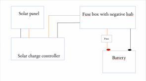
My plan is to buy a Votronic MPP 165 Duo Digital or a Victron SmartSolar MPPT 75/10. The Victron has a load output with max 10 A, and the Votronic has a load output with according to the wiring shall have no more than a 5 A fuse. At the same time, the larger Victron have no load output at all, only on + and – to the panel and a + and – to the battery.

The only place I have found that this is this video:

…where he says that you should connect the load and not to the load output of the charge controller. This sound correctly, but why does almost every scheme when I Google connect the load directly to the charge controller then? I think this may be because the load on these schemes are rather small, but I am not sure.

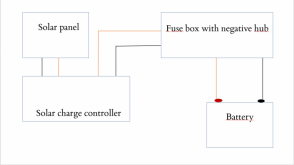
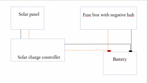
My plan is to connect the plus on the battery to a fuse box and the negative to a junction box, and from those two connect the rest, and then like this:

http://www.windofkeltia.com/eagleready.org/solar/wiring.html

except that the inverter should be my water pump and other components. As I see it, it does not matter where I connect the wires of the plus in the circuit. So instead of connecting five + cables directly to the battery I can connect those to the fuse box.

Have I missed something important here?[/MEDIA]
 
Some of the charge controllers made for smaller use like RV's and such are like this, my little PWM charge controller on my RV 12v system has the separate load output terminals as well (solar panels and charge controller had been added in later, not original equipment), and those load terminals are not being used since my factory circuit 12v loads are all connected straight to the battery via the original 12v fuse panel.

The only side effect is that the charge controller doesn't display the amps being drawn by loads. Not a big deal, I don't use the charge controller for monitoring power usage (only for charging), but it does tell me battery voltage and amps of solar charge rate, just doesn't read load information (because the loads don't feed through it).
 
Last edited:
Thank you! I plan to hade the charger and the components hidden, so I will not be able to see them anyway.

Maybe another stupid question, but that means that if I connect the load to the load output of the charge controller, the current goes from the battery, throught the charge controller and then to the different components, for example my pump.
 
Yeah, so you would also have to make sure that the charge controller can handle all the amps it was managing the load indication for. Say the charge controller load circuit was rated at 50a, so then you decided to hook your fuse block to run through it and with everything turned on in your fuse panel you drew 100a, you could potentially fry the load indication circuit in the charge controller, which could just affect that or I suppose at worse case it could fry the whole charge controller to the point where it couldn't even charge anymore.

Or you could just run one load through it. If you only wanted to read how much amps the pump draws, you could only wire that into the load terminals. You'd have to read the manual for it and see if it has a max current limit on that port before you decided whether to use it or not.

If you had a Victron charge controller, those have externally mounted shunt solution which you can add it to go in between on the fat lead directly at battery to measure current / volts, and they send information via bluetooth back to the Victron charge controller and with the phone app management they can tell you all the volts / amps / kW/h / nice graphs and everything...

1606378540441.png


There are also lots of other companies who make similar remote battery monitoring / shunt solutions to provide remote monitoring of loads, like Ali Battery Monitor for example:
 
Wonderful!

Depending on the charge controller I choose I may use the output load. The Victron MPPT 75/10 has a continuous load current of 15 A, which would be ok since my pump (the only "heavy" component I have) requires 6,25 A). However, the Voctronic (if I read this correctly: https://www.votronic.de/images/Manuals/07. Solar Current Technology/1710_1715_1720_1725_e.pdf (at p. 3) requires a 5 A fuse between the load output and the load, which makes it impossible to wire the pump that way.

So I suppose it comes to which one of these two I want, but then I at least know how to wire it.

The way I interpret that diagram, is the lead with the 5a fuse on it, is an optional lead, used to provide a reduced current to charge the starter battery.
 
Ah, so that is no "normal" load output.

But then, why does some charge controllers have these load output while some other does not?
 
It's just a feature to add monitoring as an enhancement, not a necessity for charger function... I suppose on some of the higher-end chargers like Victron or something, they might have calculations for battery SOC value to assist with charging (optional, only if you add the shunt monitoring and that input is available), but cheaper SCC will only ever determine charging based on voltages / amps rate on the charging lead.
 
I stumbled on another question about how to wire this. Due to a rather small space I would prefer to have a fuse box (for example this: https://www.amazon.co.uk/dp/B07GYTZF35/ref=dp_prsubs_2?th=1).

But how about the wires from the charge controller, can those be connected to the fuse box as well? Or do they have to go directly to the battery, and from the battery to the fuse box?

I tried to draw the wiring in the pictures. I would prefer the one where the wires go from the charge controller to the fuse box, but I am not sure whether that is possible.
 

Attachments

  • Image1.png
    Image1.png
    87.9 KB · Views: 13
  • Image2.png
    Image2.png
    94.4 KB · Views: 10
I stumbled on another question about how to wire this. Due to a rather small space I would prefer to have a fuse box (for example this: https://www.amazon.co.uk/dp/B07GYTZF35/ref=dp_prsubs_2?th=1).

But how about the wires from the charge controller, can those be connected to the fuse box as well? Or do they have to go directly to the battery, and from the battery to the fuse box?

I tried to draw the wiring in the pictures. I would prefer the one where the wires go from the charge controller to the fuse box, but I am not sure whether that is possible.

Yeah, it doesn't matter really where you bridge them in (they're paralleled anyways), as long as the all wires are sufficient gauge to handle the amps of both the fuse block loads and charge controller loads... Make sure there is a fuse or breaker protection on the charge controller to battery bus connection.
 
Yeah, it doesn't matter really where you bridge them in (they're paralleled anyways), as long as the all wires are sufficient gauge to handle the amps of both the fuse block loads and charge controller loads... Make sure there is a fuse or breaker protection on the charge controller to battery bus connection.
But that is only if I choose the one where the wires from the charge controller go directly to the battery? I will have a fuse on the positive wire from the battery to the fuse box (see picture). I am not sure if that matters in this case (since there will be fuses in the fuse box), but I have read that you should always have a fuse close to the battery's positive.
 

Attachments

  • Image3.png
    Image3.png
    101.2 KB · Views: 3
But that is only if I choose the one where the wires from the charge controller go directly to the battery? I will have a fuse on the positive wire from the battery to the fuse box (see picture). I am not sure if that matters in this case (since there will be fuses in the fuse box), but I have read that you should always have a fuse close to the battery's positive.

Yeah on any length of wire run, you want a fuse protection close to the power source, in case that wire shorted somewhere along it you won't have a meltdown.
 
Back
Top