diy solar

diy solar

how to modify a car alternator for 48v charging

i had a shower thought for an easy, yet probably not very efficient (but who cares lol) method to achieve charging from a vehicles engine.

if you're running an all in one inverter with a 240v/220v charger like the MPP solar range, use an appropriately sized to your alternator output 12v inverter on it. limit AC charging on all-in-one accordingly to not smoke your cars alternator.
No doubt round trip efficiency sucks, but the engines running anyways. This way you don't need dual alternators/voltage systems for your vehicles electrical, and if the "hotel" power system is far away from the engine at the other end of your RV/trailer, higher voltage means less current, smaller cables and less vdrop.
so if i get this right you are saying use a 12v mpp inverter powered by engine alternator to feed 220vac to a second larger 48v mpp inverter to actually
feed power to the ac panel in the boat?
 
so if i get this right you are saying use a 12v mpp inverter powered by engine alternator to feed 220vac to a second larger 48v mpp inverter to actually
feed power to the ac panel in the boat?
the first 12v doesn't have to be a MPP, can be anything.
the MPP all in ones AC input is a battery charger, so electrically you're charging your 48v batteries from the first 12v inverter, and then the 48v inverter is drawing from the 48v batteries for your AC loads.
 
That sounds interesting. Like you said, the engine is running anyway. Also, those continuous duty marine alternators that I mentioned above do come in 12v versions with higher current - not exactly double, but close.
 
That sounds interesting. Like you said, the engine is running anyway. Also, those continuous duty marine alternators that I mentioned above do come in 12v versions with higher current - not exactly double, but close.
Hello.
I half agree, because even double amp alternator still need enough rpm to cool down, I'm not in boat engines, but I suppose it's sometimes at idle rpm, and you'll need to limit your amp draw to the power the alternator can give at idle to not smoke, that's not much divided by 4 and 90% efficiency in the 1st inverter also 90% in the second.
Maybe you'll get 10 amp, without smoke /4x0.9x0.9=2.025A.
Thus 48.6Ah for 24 hours continuous duty.
Is it enough for your battery bank?
Maybe I'm too conservative with 10 amp, but I know that alternators are not good at low speed.
I hope it helps. Maybe you never run at idle, in that case don't mind my intervention, I'll be smarter another time. :D
 
Just on a theoretical basis. Alternators are three phase. If you wired those three phases into two 24V to 120V transformers, that would get you close to the right voltage and it would be isolated.
That wouldn't work too well, power transformers are designed for 60 cycle power. The AC frequency of the alternator power depends on the speed it is turning, but will be MUCH higher than 60 cycles at any normal operating RPM.
 
Theoretically, it would be possible to get about 36V. If you put rectifier to every phase (capacitor too) and conected dc output of every phase in series. You would need to isolate every phase (disconect original delta or star configuration) but from every phase you would get about 12V so in series it would be 36V plus some kind of buck boost to get that 48V. Only problem would be 12V rotor but you could use output of one phase or another alterantor or add maganets to rotor.
 
If you take the 160 Amp alternators for Yukon of Escalade and remove the diodes and regulator and manually change the field you can get them to put out 58V at around 80 amps...

The Ford Large Case 1G alternators work too but they make a lot of fan noise...
 
does anyone no if you can modify a car alternator to charge a 48 vdc battery bank
Since 48 or 24V seems optional to you, how big is the boat? And what requires a 48V battery?

I’m just curious regarding the need for 48V if merely a second alternator at 24VDC (or 120VDC with a charger) would function fine. Plus 24- or 48V is not required in many circumstances
 
Since 48 or 24V seems optional to you, how big is the boat? And what requires a 48V battery?

I’m just curious regarding the need for 48V if merely a second alternator at 24VDC (or 120VDC with a charger) would function fine. Plus 24- or 48V is not required in many circumstances
Those are my thoughts, too...
you increase the voltage to limit line loss when you're running cable.
If you had short, thick cables from the alternator/batteries to the inverter, a 12vdc system would work. And those alternators are available all over the place...
Heck, even 24v alternators are common enough for aircraft and marine duty. (even HGVs in Europe)
 
Winding of alternator are of a particular gauge, so current is limited by resistive heating.
I think 24V or 48V operation can be a way to get more watts out of it.
I used to see gadgets advertised to disconnect regulator and get 120V for power tools.
At some point, magnetic core may be the limit.
 
I keep looking at this, need something to control the field current of the alternator based on the charging characteristics of the battery.


Possibly use a 48vdc secondary alternator and a wind/hydro charge controller? I suspect their MPPT will not work correctly with an engine running the alternator.

Use a generator head with a separate inexpensive charging inverter that allows great flexibility in frequency/voltage?
 
Last edited:
so if i get this right you are saying use a 12v mpp inverter powered by engine alternator to feed 220vac to a second larger 48v mpp inverter to actually
feed power to the ac panel in the boat?
I've already done this for my truck camper last year, I installed dual alternators for 355A of 12V charging. I also installed a master switch under the hood and a precharge circuit. I ran 2/0 cable under the body to the rear of the cab, I have a 12V Giandel 2400W inverter installed there, back seat has been removed and I have a platform with a CFX95 freezer/fridge there. Next, I ran an RV cord back thru the floor to the rear bumper of the truck and installed a 30A RV receptacle.

I made a short cord with the remaining RV cord and can plug in my Growatt 24V 3000W inverter. I set charging at 60A, 1440 watts. Works well, I've tested it and quite impressed. Some efficiency loss, but I can shove a pile of amps downstream, even run the camper if the Growatt went down.

I should take photos when I get the truck back out and start a thread for it.
 
I think you're better off getting a chargeverter from eg4 and limiting the output to whatever your cheap generator can sustain. It might be able to be done cheaper but you could blow the battery bank too... the cheap does come out expensive sometimes.
 
If you take the 160 Amp alternators for Yukon of Escalade and remove the diodes and regulator and manually change the field you can get them to put out 58V at around 80 amps...

The Ford Large Case 1G alternators work too but they make a lot of fan noise...
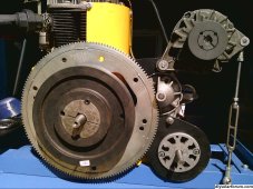
An ordinary garden variety 12v vehicle alternator needs to turn at about 2,000 rpm to charge a 12v battery.
The alternator pulley is usually about one third the diameter of the crank pulley, so as long as the engine idles above about 650 rpm the alternator light will go out, and the battery will be charging.

To charge a 48v battery the alternator will need to turn at four times the rpm or around 8,000 rpm which it will very easily do.
When fitted to a typical modern engine that might rev between 650 rpm to 6,500 rpm, the alternator will be whizzing aroud between 2,000 rom and 20,000 rpm which it will do very reliably. So running an alternator continuously at 8,000 rpm to charge a 48v battery is not a big deal.

Mechanically its not an issue, but it will require a 48v voltage regulator that you will probably have to make yourself. The field winding might require about four amps at perhaps 8v to 10v for full max rated output, and that will require a bit of thought.

This all becomes attractive because its relatively cheap to do, especially if you can score a free alternator, and figure out how to turn it at 8,000 rpm plus.

There are alternatives..... Some busses, trucks, and earth moving machinery often come with 24v electrical systems and larger alternators.
If you can find one of those, it should work fine at 48v needing only about 4,000 rpm, and once again a home brew regulator.

Its also possible to use a bog stock 12v alternator, rip out the diodes, and fit a voltage step up transformer to each phase. This will be a lot easier, and a lot more practical than rewinding the alternator itself. Its theoretically possible to run the original alternator at less than 2,000 rpm with suitable transformer ratio, but it will be limited in power output. While there will still be full rated amps availabe, less voltage and less rpm means reduced power. It may still be enough to be useful. It depends what you want to do.

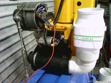
Another totally different approach to charging a higher voltage battery (48v and above) would be to use a treadmill motor.
Here we have the exact opposite problem. A treadmill motor rated to run at 180v and 4,500 rpm and 12 amps can be run at one third the speed, so we then have 60 volts, 12 amps, and 1,500 rpm as a motor.

Used as a generator it will need to be run faster, perhaps at 2,000 rpm, as a guess, to charge at the full 12 amps and reach 60 volts.
That may be more attractive than a vehicle alternator for lighter duty work, and it has the advantage of not needing a field winding.

Many ways to skin a cat.
 
Think the 3 phases of alternator windings, presently wired Delta, could instead be wired zig-zag to produce single phase at double voltage?
 
Think the 3 phases of alternator windings, presently wired Delta, could instead be wired zig-zag to produce single phase at double voltage?
I once disconnected the three separate star windings, connected each winding to its own bridge rectifier, then connceted the dc side of the three rectifiers in series. That gave me exactly double the original dc voltage of the original, and with very low ripple voltage too!

If that was done with a 24v alternator it would be perfect for a 48v battery.
Thanks for reminding me.
 
I think it will work the same if you put rectifiers on output of the zig-zag, rather than on each winding.

What makes it low ripple? I'd expect rectified 3-phase to be reduced ripple. Oh, adding magnitude of projection of vector, rather than vector with it's polarity, may be what did that.

If you had put capacitor in addition to rectifier on each winding, then you should get 3x the voltage. Given sufficient capacitance, of course, to reduce ripple.

I came across zig-zag when looking for ways to make a central neutral from a delta-wound transformer. There are zig-zag transformers for that purpose. Another approach I thought of was center tap transformer across one side of the delta, and transformer with 1:2 turns ratio from that center tap to opposite corner.
 
A six diode three phase bridge rectifier only has around 2% to 3% ripple voltage because the waveforms overlap so much up near the peaks.

This three winding, three bridge rectifier system (twelve diodes total) works in pretty much the same way, and the output waveform looks the same as well, its just at twice the output voltage. I have some photographs of the whole experiment, including oscilloscope traces here on an old hard drive somewhere, but cannot find it right now.

I did find some pictures of my treadmill motor battery charger though. That works very well, ten amps at around 100v dc for my thirty lithium cells.
It did require an e-bay 12v bilge blower to cool the treadmill motor. They are not normally very well ventilated, and become unhappy when run continuously at full rated current.
 

Attachments

  • 2020-01-01_0002.jpg
    2020-01-01_0002.jpg
    1.3 MB · Views: 8
  • 2020-01-02_0002.jpg
    2020-01-02_0002.jpg
    1.7 MB · Views: 8
Back
Top