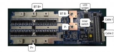
I have a Spelos 48v 200A 16S BMS (see link below) and this BMS has three contact/ screw points on a bar strip (see the attached jpeg....BT B+ and P+) for connection of the battery negative (B+) and inverter side positive (P+).
I have a few questions on the purpose and options with connection as it relates to this BMS.
1. I am connecting the battery and inverter (Growatt SPF5000TS HVM) to the BMS with 2/0 AWG and looking at the BMS I am wondering why it has so many points on the positive side for connection (3 x 2) and why is it not the same on the negative side?
2. To get a good connection with the 2/0 AWG wire lug that I will use, I am thinking of fabricating two copper busbars to run across the two BMS strips (BT B+ and P+ in the jpeg) and joining each of those busbars with three screws. This in turn will allow me to get a stronger contact at the busbar with a 2/0AWG lug.
I see also that some people run multiple smaller wires to the terminal points on the BMS but this still means that I have to bring those points together at the battery and inverter terminals and as I have the 2/0AWG wire this would seem like another potential failure point. Which is the better option a) the busbar with a single large wire b). three smaller wires connected to the BMS and coming together as one lug on the battery or inverter?
3. If I run multiple smaller gauge wires between the battery, BMS and then inverter what size wire would I need to use to match the 2/0AWG wire?
4. What extra functionality do I get running both positive and negative thru the BMS vs say some of the Dalys where I only see a single wire connection on the negative side?
The 2/0AWG wire sizing (vs the 200A BMS) is me being cautious and thinking forward for when I eventually add additional capacity.
Thanks for help.
CAN BUS RS485 48v 200A 8S-16S lithium iron phosphate lifepo4 bms monitoring system battery management system


