diy solar

diy solar

How to repair a Growatt SP2000

paulca

New Member
Joined
Sep 13, 2022
Messages
77
How to repair a Growatt SP2000.

DISCLAIMER: This worked for my SP2000, which had a PV Short Circuit fault , it may not work for yours. but, having said that if one of your IGBT’s is blown, it’s probably the cause of your issue, and it’s relatively simple to test; a bit more complex to fix.

Before attempting to dismantle the unit ensure you've followed the official shutdown procedure and have disconnected the PV, INVERTER, AC and BATTERY from the unit. THERE MUST BE NO CONNECTIONS to the unit.

If you have any unused/damaged growatt kit you no longer need, please PM me. I'm researching different faults on these units and hope to write a 'how-to' repair guide for any I can get my hands on.
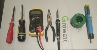
  1. Tools required : Philips screwdriver , Torx T15 screwdriver, Multimeter, pliers, soldering iron, solder, de-solderer
    1664642534754.png


  2. Get an empty egg box to put your screws in, work top left to bottom right, like reading a book.
  3. Remove the 2 thumb/butterfly screws holding the black steel shroud that surrounds the base of the unit Put the screws into egg 1 position (top left of the egg box). The shroud comes off by sliding it sideways , then pulling out.
    Q2XIRKVLulJtdP6SDHkzfwD7n39fp8xTZXRQ_ftOyhoZOi4OIocMHV3H_ls_o1pu6KfbT237nsqBw_tidFZUTHCreI3hvdfpQGZ0rAdwTsWc7Lfg7UHZ37CSlh3i7_84TRPsYvYOvk8eVQ9zr-HOkWNvmMEglfWbRXOiVEvwAdUOOQd_sApSeg8NJQ

  1. Using the torx screwdriver remove the 8 screws that hold the face on, 3 top, 2 sides, 3 bottom. Also stick them in egg 1 position.
    05S8_OJZv8NlCsoXoNYrN3Y0i_hBR0G8TKBTTiCTPsgODRlHQhBnMBoMPeLxqE-qM9hSw5TDhjIiMjgoUKD7u2HnXC23-6bwJEUUTjVAl_qtcMrJZ3hR5SeRigF6eyovtyML5amsUYflLbcvXUjIDxym-gEp5sWzKONyMoJtH6uFvOzi_NWQLmU_OQ


  2. Remove the face by lifting straight off.
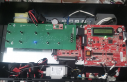
  3. Now it looks a bit terrifying with the face removed, but don’t panic, you’re now only a few screws away from testing the IGBT’s
    1664705375928.png
The tiny red board on the LED board will only be on yours if you have SP-CT antenna.

  1. Remove the 3 screws holding the green LED board in place, disconnect the ribbon cable by gently pushing the 2 retaining lugs outwards….screws in egg box 2....place the LED board to one side.
  2. Next, remove the 6 screws securing the aluminium mounting plate for the daughter boards. Theres 2 left 2 right which are obvious, and 2 in the middle between the red boards which aren’t immediately obvious….screws in egg box 3
    6APC8h5QcivbkjCYh39NCMAmIIY6v3w6aVuSDZHvQZzwGKNtbb6lMM5JhlEZ3N_E2S7gofeE3sxiCxFjgrHatMI2C7bMZUksMf55ynQAVt83UV5ZsSCvs70i8AwUvRBnDCkecTHQfcf2YWPIaeonHqqseFpMvBQx33eIrbuARyuvNDZbQ_NP4e4yNw


  3. You need to disconnect the 2 ribbon cables on the top and bottom of the left red board in the above pic, then the whole assembly should lift out. I was lazy and just left the other connections on the right board attached and let it dangle in front of the unit, but if you're less lazy you can disconnect them, just take a photo before you do so you know which connector goes where.

  4. NOW you can see all the transistors, there’s 11 of them in total, and 2 different types, but the testing procedure is the same for each.The high power transistors run around the top and bottom right edges of the mainboard. Each transistor has a white plastic block securing it to the heatsink at the back.

    TOP ones (6 of)
    OPi5g_SPpFbRprkyroHK7ycprQspV-h7cv4Flz9WIVeHAbc6H9gigoPz4LyEheCLw1uXaCByBM5rjANpZBn7J8Py49ivG_BLbvKhkU8fCGNW8fneUDFJ17llroifWvX-QSW85ezwi4tuAKc7g03YVPXvmWDd3L48jW06PY6cvdh0cAIMF3e2YE9bIw


    BOTTOM ones (5 of)
    mTNtuEi8gYnZbOJUmlo6zJ3e8VUuDXnSBYsW-hdtL7iYMp7I4JJBOOw_9Sl5xratvDpzyeYb0_r9w_7HX-tdpTGu--yoqphewwJ8_52u89vfgDQNgU7XgSCi2MJT4YxHy48uaDqewJPL8mtx6T-6TjpjL7LYmhH6bx7NdFC1ucEH97Xc7x1vzXwWCw


  5. Each transistor has 3 solder connectors on the board, marked G,_,E top row, G _ S bottom. Put the multimeter on diode setting, and place it across the S/E and the middle pins with the red on the S as shown below. The board may be varnished,so push hard.
    6hpiWxDwN_hkmtB8YDAKtxaQQGR1OGCz2Q8TsS-gEFe3Er-y6vGv6Al-pE35GsF_U4JXws4myqCF_SsJy7wieMrUa7AQ3llEU5hYNgdWjU-SSSQBI5PruN6Y8iESyDP4Rag6qGmHyrgcYDsvA19YN7EvJ-2fwN8Bb9GKj3lcZ6Z-hzDJzm4xHRn4xQ
    You should get a reading of roughly .440 and the top ones should be .390 ish.
So, if they all read OK and there's no shorted connections, the transistors are OK and the fault must be elsewhere.
If you've got a shorted one , or open circuit one, move onto REMOVAL below.
 
Last edited:
  1. REMOVAL

  2. So now you need to remove the board, start at bottom left and undo the PV and INV connectors
    3Xii_13_UyareJqElWeBPj0DwOWAjAQwvEjZcgH7ZN8ST5x099qqndU4fkn8L73uO05u7-kzdNUwetHl9gSCk3K63dJUuw66aFRMmJv_cx0DmuKyUBxh2-uNzxNG2WRI49DQNuK_5pWNnTi_TTGPeYjQv3U2QaTC4eVGrh07RTjdiG_mZuJJNEby9A


  3. There’s a little circuit board which comes off, set it to one side, screws in egg box


  4. Next remove the 2 AC pins, black on the right , red on the left.
    Nj1BXWb06VoPa3hrxFE1T8OXS4HT46z3p0tfgYp7estkg8RJlzaOCu2nSZHeY-cttQzOzn1MCKEndKyyYGlUkcGSaI2fYrxSfhtWm93WB9fXmHP0g0tNLlpkkIXItPYFWU5GjgBqjauJ7KxWveTcKxVmMs90PQ-0ZLxnA7gnH0E6kGgXLZn1K5ROuw


  5. Next remove the spade connectors top left, they need some pulling, black top , red further down. NOTE on mine the red was labelled P07, but it in fact connected to P06 on the board....Growatt trying to confuse us ? who knows.
    Y0kJBj0B0OtuXh8le3JGl4sShXDVs8tm2Y2KSvcamCHgjh9oF0ZwG58RE6_FmVLYMbPnrZjndP50CHHsA140ORz-UsiSyz3_q5nBklh0QhVVGj1Q1u6gRLvkZleyvThzWFi-8BPCIt4g212DWKr7SWW-AW5znSEcChJHC-bhJU5jlGFge1OC65KkBw
  6. Next unscrew alll the 4 blue and black connectors , screws in egg box 5.
    ceGL4iLgTF7-6vfYrWtGLuLOxDwAcd-mLlwOeU3aDviD5FUrqoORm_k2O_jr9d_LSsBVmXaOoWiBqZnco-WiNXDbmEd1EzcyaIhfF4emsVvH1Yp6yf768wtuH5NdUyV5BV3JbgWN59oLAsBMwNu1YmPDOOsnKFW4DaP4DDyNrSj0a3jIvywCYWBS9Q
  7. Next the battery terminals , egg box 6..
    pne9IIw3PXAp2JvKFOo5yl0lKxf9uqWyOpprkgVd3g91XVpG5qBz6TPY5HCfBwksp_07wOpkLn5nk4SCYxee_0a2b8I50UCyvgibbMtE5zripp_ynwPEChFNZQU0GXdE0Mov3-UWg8edeesisAnmPnpegHd1QtT6xPRf8kGXxHB3a0-DxnRxYPU0zQ
  8. Disconnect the CT sensor ,NTC sensor and earth connectors taking note which goes to which.
    B--b7FCgdPsyMijK6RMnKeJyPnr4mRJ_ZO1NIbJ9zwKeNnRR2WX-I4miRICc5kn_1hhmqNLNjZaWX6hD8KggJT3wTkMjznjfpqA7QnKTTKwOPMpJ2V2gsRb_zS_76PsqdZRaDAPoR8d_H6UQIqzAHOJcF9t4Yqj5ks0jhZ7K7kYgW7lR_TdYMLFKjQ
  9. Theres another earth connector at the top
    lXwzF2ozEJR2_jyTe3rGoLTfwtWj-AdQvzWrEkaFamn5odQoWBQgKOy6Ue9kEioQtk2IM87iPxU239aDIN_IYlxkJpduWNlN570ky4ov1t_Ka4ZC_gj8POmU0r0Iltod6NaRCy_0yLNm901DjFxnP6GeJVnZkjX-5w6JaT-xJrxuWx4fsDRCzILmrQ
  10. I think that’s it for disconnecting, so now remove the long screws from the white plastic blocks holding the transistors to the heatsink(11 of)…. There’s also one screw at the bottom left in a white plastic block which fastens a high power diode to the heatsink , 12 screws in all into egg box 7
  11. LN5ZNFzS9pnz6kH5Cxz8NrsF9M9_W4ny34Jbw58au4t8BRe02KwVuZwKc7Kf-ys3XoVpBr4A2jsppbJrsgme1_vfo7Ii5LIgAjXmvnM6KiWUd-WLnvUcGEm503u3Bv09IHmZTC6u2DweyWIKG1229MgkItK2xfQD2etg0nhPrpcbXVTjfkqX_01lPw
  12. Now remove all the screws holding the board on, there’s 7 screws, and 2 long risers, you’ll need some pliers to unscrew the risers, all can go into egg box 8.
  13. Now , you’re ready to remove the board. Be absolutely certain you’ve got all the screws out …. I was convinced I’d missed a screw somewhere as the transistors are stuck to the heatsink with little pads and it requires quite a bit of force to get them off. I was worried about flexing the board too much, so I started near the PV connectors, worked my fingertips under and just kept teasing it, then I’d try somewhere else, bit more teasing , eventually it will pop up.
  14. Now , desolder the dodgy transistors, hook some insulated wire through the hole in the transistor , apply gallons of solder to the pins so they’re all bridged, and once it’s all molten pull the transistor out. You might need to turn the heat up on your iron as the heatsink on the transistor does a cracking job of dissipating the heat.
  15. Use the de-solderer now to remove all the solder you just applied so that the holes are clear.
  16. Install the new transistor. Use the plastic block to line it up with the others. It needs to be in the same place as the old one, as the screw needs to go back in. Make sure the soldering iron is below 300 degrees if you've turned it up for removal. The max lead temp on these chips is 300. Once in position solder on BOTH sides of the board. The plastic block has a little bit of play in it, maybe 1mm in each direction, so it doesn't need to be micron perfect.
Reassembly is the reverse …. just scroll up , and work your egg box bottom right to top left ;).

Now, strictly speaking if one transistor is gone, you should replace the whole row with new and use new heat pads …. but at £5 a pop I decided just to replace the 3 that had blown on mine and re-use the heat pads…tbh…I wasn’t sure if the gate controller chip would be damaged so was keeping expenditure as low as possible.

REPLACEMENT TRANSISTORS :-

Bottom type:-
https://uk.farnell.com/infineon/irfp4110pbf/mosfet-n-to-247ac/dp/1602244
Top type:-
https://uk.rs-online.com/web/p/igbts/8648782

Hopefully this will help someone else with their broken Growatt's , If it does , please leave a comment , and I'll know my effort wasn't for nothing.
 

Attachments

  • 1664705513947.gif
    1664705513947.gif
    42 bytes · Views: 14
Last edited:
  1. REMOVAL

  2. So now you need to remove the board, start at bottom left and undo the PV and INV connectors
    3Xii_13_UyareJqElWeBPj0DwOWAjAQwvEjZcgH7ZN8ST5x099qqndU4fkn8L73uO05u7-kzdNUwetHl9gSCk3K63dJUuw66aFRMmJv_cx0DmuKyUBxh2-uNzxNG2WRI49DQNuK_5pWNnTi_TTGPeYjQv3U2QaTC4eVGrh07RTjdiG_mZuJJNEby9A


  3. There’s a little circuit board which comes off, set it to one side, screws in egg box


  4. Next remove the 2 AC pins, black on the right , red on the left.
    Nj1BXWb06VoPa3hrxFE1T8OXS4HT46z3p0tfgYp7estkg8RJlzaOCu2nSZHeY-cttQzOzn1MCKEndKyyYGlUkcGSaI2fYrxSfhtWm93WB9fXmHP0g0tNLlpkkIXItPYFWU5GjgBqjauJ7KxWveTcKxVmMs90PQ-0ZLxnA7gnH0E6kGgXLZn1K5ROuw


  5. Next remove the spade connectors top left, they need some pulling, black top , red further down. NOTE on mine the red was labelled P07, but it in fact connected to P06 on the board....Growatt trying to confuse us ? who knows.
    Y0kJBj0B0OtuXh8le3JGl4sShXDVs8tm2Y2KSvcamCHgjh9oF0ZwG58RE6_FmVLYMbPnrZjndP50CHHsA140ORz-UsiSyz3_q5nBklh0QhVVGj1Q1u6gRLvkZleyvThzWFi-8BPCIt4g212DWKr7SWW-AW5znSEcChJHC-bhJU5jlGFge1OC65KkBw
  6. Next unscrew alll the 4 blue and black connectors , screws in egg box 5.
    ceGL4iLgTF7-6vfYrWtGLuLOxDwAcd-mLlwOeU3aDviD5FUrqoORm_k2O_jr9d_LSsBVmXaOoWiBqZnco-WiNXDbmEd1EzcyaIhfF4emsVvH1Yp6yf768wtuH5NdUyV5BV3JbgWN59oLAsBMwNu1YmPDOOsnKFW4DaP4DDyNrSj0a3jIvywCYWBS9Q
  7. Next the battery terminals , egg box 6..
    pne9IIw3PXAp2JvKFOo5yl0lKxf9uqWyOpprkgVd3g91XVpG5qBz6TPY5HCfBwksp_07wOpkLn5nk4SCYxee_0a2b8I50UCyvgibbMtE5zripp_ynwPEChFNZQU0GXdE0Mov3-UWg8edeesisAnmPnpegHd1QtT6xPRf8kGXxHB3a0-DxnRxYPU0zQ
  8. Disconnect the CT sensor ,NTC sensor and earth connectors taking note which goes to which.
    B--b7FCgdPsyMijK6RMnKeJyPnr4mRJ_ZO1NIbJ9zwKeNnRR2WX-I4miRICc5kn_1hhmqNLNjZaWX6hD8KggJT3wTkMjznjfpqA7QnKTTKwOPMpJ2V2gsRb_zS_76PsqdZRaDAPoR8d_H6UQIqzAHOJcF9t4Yqj5ks0jhZ7K7kYgW7lR_TdYMLFKjQ
  9. Theres another earth connector at the top
    lXwzF2ozEJR2_jyTe3rGoLTfwtWj-AdQvzWrEkaFamn5odQoWBQgKOy6Ue9kEioQtk2IM87iPxU239aDIN_IYlxkJpduWNlN570ky4ov1t_Ka4ZC_gj8POmU0r0Iltod6NaRCy_0yLNm901DjFxnP6GeJVnZkjX-5w6JaT-xJrxuWx4fsDRCzILmrQ
  10. I think that’s it for disconnecting, so now remove the long screws from the white plastic blocks holding the transistors to the heatsink(11 of)…. There’s also one screw at the bottom left in a white plastic block which fastens a high power diode to the heatsink , 12 screws in all into egg box 7
  11. LN5ZNFzS9pnz6kH5Cxz8NrsF9M9_W4ny34Jbw58au4t8BRe02KwVuZwKc7Kf-ys3XoVpBr4A2jsppbJrsgme1_vfo7Ii5LIgAjXmvnM6KiWUd-WLnvUcGEm503u3Bv09IHmZTC6u2DweyWIKG1229MgkItK2xfQD2etg0nhPrpcbXVTjfkqX_01lPw
  12. Now remove all the screws holding the board on, there’s 7 screws, and 2 long risers, you’ll need some pliers to unscrew the risers, all can go into egg box 8.
  13. Now , you’re ready to remove the board. Be absolutely certain you’ve got all the screws out …. I was convinced I’d missed a screw somewhere as the transistors are stuck to the heatsink with little pads and it requires quite a bit of force to get them off. I was worried about flexing the board too much, so I started near the PV connectors, worked my fingertips under and just kept teasing it, then I’d try somewhere else, bit more teasing , eventually it will pop up.
  14. Now , desolder the dodgy transistors, hook some insulated wire through the hole in the transistor , apply gallons of solder to the pins so they’re all bridged, and once it’s all molten pull the transistor out. You might need to turn the heat up on your iron as the heatsink on the transistor does a cracking job of dissipating the heat.
  15. Use the de-solderer now to remove all the solder you just applied so that the holes are clear.
  16. Install the new transistor. Use the plastic block to line it up with the others. It needs to be in the same place as the old one, as the screw needs to go back in. Make sure the soldering iron is below 300 degrees if you've turned it up for removal. The max lead temp on these chips is 300. Once in position solder on BOTH sides of the board. The plastic block has a little bit of play in it, maybe 1mm in each direction, so it doesn't need to be micron perfect.
Reassembly is the reverse …. just scroll up , and work your egg box bottom right to top left ;).

Now, strictly speaking if one transistor is gone, you should replace the whole row with new and use new heat pads …. but at £5 a pop I decided just to replace the 3 that had blown on mine and re-use the heat pads…tbh…I wasn’t sure if the gate controller chip would be damaged so was keeping expenditure as low as possible.

REPLACEMENT TRANSISTORS :-

Top type:-
https://uk.farnell.com/infineon/irfp4110pbf/mosfet-n-to-247ac/dp/1602244
Bottom type:-

https://uk.rs-online.com/web/p/igbts/8648782

Hopefully this will help someone else with their broken Growatt's , If it does , please leave a comment , and I'll know my effort wasn't for nothing.
Nice work that paul well done. All saved for future reference?
 
Hello. Very helpful. I spotted this and decided to have a go at my non working sp2000. The pv led is not lighting up , and it won't charge or discharge, so I thought I would have a go. Having removed the board, it became obvious that someone has carried out the repair you have described, and changed all of the mosfets. One thing I have noticed is that the top and bottom transitor types are the opposite way round to the ones you have posted links for. All of mine appear to test good, although I don't profess to be an electronics expert. There is another transistor to the bottom left of the board connected to the pv input. Mine appears to be a double diode rectifier , and I cannot understand why this would be connected to the pv input. Is it just for reverse polarity protection, the wrong thing, or just me being thick. Thank you in advance for any ideas.
 
Hello. Very helpful. I spotted this and decided to have a go at my non working sp2000. The pv led is not lighting up , and it won't charge or discharge, so I thought I would have a go. Having removed the board, it became obvious that someone has carried out the repair you have described, and changed all of the mosfets. One thing I have noticed is that the top and bottom transitor types are the opposite way round to the ones you have posted links for. All of mine appear to test good, although I don't profess to be an electronics expert. There is another transistor to the bottom left of the board connected to the pv input. Mine appears to be a double diode rectifier , and I cannot understand why this would be connected to the pv input. Is it just for reverse polarity protection, the wrong thing, or just me being thick. Thank you in advance for any ideas.
Yes @David Crofts I think that diode is simply there to stop current flowing back out into the panels, can't see any other reason for it. Perhaps I got my instructions wrong regarding the 2 transistor types , have slept a lot since then , but I've still got one in bits in the garage so I'll go double check.
 
You're right @David Crofts , as you know, you have to flip the board over to see the FET's , so top became bottom for me.
 
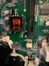
Hello, hope this is the right place to put this request, but I'm trying to locate a replacement transformer for one (TX2) on my SP2000 main board. Was wondering if anyone had a burntout board beyond repair that has a good replacement part they would consider parting with?
 

Attachments

  • SP2000-Trans.jpg
    SP2000-Trans.jpg
    96.8 KB · Views: 0
Back
Top