diy solar

diy solar

I Flipped the Switch on my Over Paneled MN Classic & Array Upgrade Today

MrM1

I'm Here, But I'm Not All There
Joined
Mar 1, 2021
Messages
2,422
Location
N. Central FL
Been working on it and planning it for a while. And it just so happened to work out that the day I actually finished the job was also my Birthday ... today ?

I have a single Midnite Solar Classic 150. For the past four years it has been just fine with a MS Classic Sizing Tool sized array. With my 24v system, I was able to use REC 285w panels in a 3s3p arrangement. Input voltage is around 104v dc.

But upgrading to a 690Ah 8s3p LFP battery bank, cloudy days, and winter days were not seeing full charge. No big deal ... LFP, but I did discover you can over panel the MS Classic. The resources here, and also email conversations with Midnite Tech said it was no problem to double the size of the array. So I found a deal on 9 REC 290w panels (same model ~ TwinPeak II ~ and almost exactly speced the same as my 4 year old 285s) so I picked them up back in Oct. Finally got around to installing them this past week, wired up them to the new MS 3 string combiner box home run last night, and connected them to the PV busbar in the MS ePanel this morning with the original array.

"Flipped the switch" at 9:15am this morning. The original array was producing 555 watts, The new array was producing 420 watts (some shading still on that side) and the total array was up to 1015 watts at 9:15am. Nice. Nearly double the morning production.

Long store short, the end result was pretty much as expected. By 10:30am I was up to 2600 watts, and 94 amps from the Classic ~ which is it's max. The weather was partly cloudy. I only saw 1800 watts the day before wiht the old array in blue skys at solar noon. So all was good. At 2600 watts and 94 amps the Classic began to clip as expected. As Midnite tech had told me, this will not hurt the Classic, it would just not use the extra power. I switched off both arrays one at a time to see what I was really producing. Some where around 3100 watts was my real production, but I knew the Classic would not and could not use it all. That's OK.

My only issue was a little more heat than i have ever seen on the FETs. MS Tech told me the Classic would not dissipate the extra power as heat, it just would not use it, In the past I have only every been able to get no more than 60ish amps of charging from my old array. This new double array hits 94 amps even on meh days. So the SCC is running pretty much wide open 94 amps for 3-5 hours per day. The FETs, which I have never seen getting above 65c where running at 85c +.

Everything went great and worked exactly as expected. This gives me what I wanted, a 5131 watt array that will produce 94 amps (the Classics Max at 24v) and will do it all day for 4-5 hours a day. But I am wondering, are temps being upwards of 90c on the FETs a bad thing? I was getting 48c on the case even with an external fan (that I have had installed for years). I read that Mosfets can do 175c but really start shortening their life at 125c (but this info was not specifically SCC data). I have no idea.

I am considering using Midnite's Charge Current Limiting programing feature (not the same as the output current setting). This would limit charging amps, but would not limit load amps if needed. Most of the time the hi amps will be from charging as I seldom use much load thru the day.

But what are your thoughts on FETs getting upwards of 90c on the classic? Is that just the result of the Classic outputing 94 amps or is it also do to over paneling? Should I Limit charge current some to off set this heat? Would that help? What would be an acceptable FET temp for 4-6 hours a day? ( my other option is a second classic obviously) Responses appreciated. @Robin Gudgel @SpongeboB Sinewave

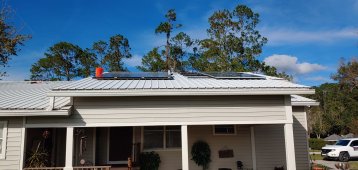
Here's some install Shots (new array is in the back of the pic)

ProSolar Racking
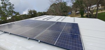
1216211402_HDR.jpg
1217211445.jpg


Both Arrays: 3s3p. Old is 2565w / New is 2610w
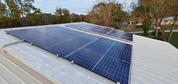
1217211703a_HDR.jpg


New Combiner box and home run ready for a 2nd Classic if I ever decide to go down that road.
(right now both are feeding a single classic)
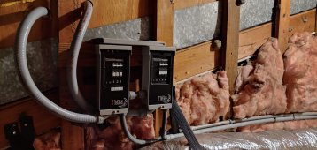
1218212054_HDR.jpg


With Midnite Solar ... It's Always Fun and Easy. ?
 
Last edited:
But what are your thoughts on FETs getting upwards of 90c on the classic? Is that just the result of the Classic outputing 94 amps or is it also do to over paneling? Should I Limit charge current some to off set this heat? Would that help? What would be an acceptable FET temp for 4-6 hours a day? ( my other option is a second classic obviously) Responses appreciated. @Robin Gudgel @SpongeboB Sinewave
First of all, Happy Birthday ?
Secondly, IMO, if the manufacturer says that's OK to run it at full spec, then I would feel comfortable running it that way. (Otherwise, what is the point of having ratings on this gear at all?)

Having read a few MOSFET data sheets, I could see the switching performance get a little wackier as the junction temps rise, but I would think that they would hit a more or less steady state in a matter of minutes when run under your conditions.
I assume there are some largish capacitors on board that are probably going to be the weakest link in terms of long term performance at high temps? I seem to remember Midnite offering some sort of "refurbishing" service for about $150 where you could send your CC in and they would replace some components that age faster than the rest and thus extend your warranty by an additional couple years.
 
Over paneling an MPPT will make them run hotter and you are seeing this of course. It has to. This is because to reduce the output amps, the input voltage has to be raised higher than its Vmp and now, the input current and voltage are higher (multiplied together) so it will have to dissipate some more. At around 90 degrees C FET temp, the Classic will reduce its output current by about 5 amps each time to keep the FET temp from rising much more. So, it is not quite as simple as someone might think but the extra unused power does not get dissipated, exactly. But somewhat.

As far as I know, MidNite will swap out electrolytics or whatever but I have not heard anything about that recently so I'm not sure about the policy there.

When I hear about over paneling, I do tend to squint and flinch a bit but probably unnecessarily. The Classic is pretty robust.

boB
 
If I manual set the Classic to output less amps either via the output setting or the MN global charge current limiting "hack" white paper will that cause the FETs to run cooler, or will the FETs Temps just continue to rise until about 90c and output gets reduced?
 
Last edited:
First of all, Happy Birthday ?
Thanks

Secondly, IMO, if the manufacturer says that's OK to run it at full spec, then I would feel comfortable running it that way.
When I hear about over paneling, I do tend to squint and flinch a bit but probably unnecessarily. The Classic is pretty robust.
And thx for these responses.

I am basing my knowledge on my understanding of the email discussion I had with MN tech Todd. In response to my over paneling question MN tech emailed me

With extra PV wattage, the Classic simply does not demand it from the panels. No extra power is generated into heat, it simply stays at the PV array. The Classic “pulls” what it needs to charge the batts or to charge the batts and support a concurrent load.

the extra wattage will not harm the Classic, it will just go unused during most of the year
I hope I am understanding this correctly.

I also plan to add another exterior 12v pc fan on the classic. I am triggering them on an off with the classic aux control
 
If I manual set the Classic to output less amps either via the output setting or the MN global charge current limiting "hack" white paper will that cause the FETs to run cooler, or does the excess still have to be disbursed as heat.

Yeah, it should run cooler at lower output current. This might be a good experiment to try.

Obviously, you want more output than you would get on a cloudy day with your normal PV array. I would start by changing the current limit to something in-between your maximum expected output current or power and the 94 amps you are seeing. Just for this experiment.
Then check the FET temperature. But to be a fair comparison, the irradiance should be similar for your 94 amp scenario here and the test case with reduced current limit.

I do not remember specifically testing this myself with PV (probably have actually) but every Classic is tested briefly in this condition and then runs a 4 hour (at least) active burn-in.

BTW, many people do over-panel their charge controllers these days because of the lower price of PV. Seems to work OK as far as I know.

Over-paneling would be a relative thing I would think. I certainly would not try hooking up say, 500 kW of PV to a single Classic. But in reality, that probably isn't much different than what you have done, electrically since the voltage would be the same. Please let me know if you try that !! :)
 
Last edited:
Yeah, it should run cooler at lower output current. This might be a good experiment to try.

Obviously, you want more output than you would get on a cloudy day with your normal PV array. I would start by changing the current limit to something in-between your maximum expected output current or power and the 94 amps you are seeing. Just for this experiment.
Then check the FET temperature. But to be a fair comparison, the irradiance should be similar for your 94 amp scenario here and the test case with reduced current limit.

I do not remember specifically testing this myself with PV (probably have actually) but every Classic is tested briefly in this condition and then runs a 4 hour (at least) active burn-in.

BTW, many people do over-panel their charge controllers these days because of the lower price of PV. Seems to work OK as far as I know.

Over-paneling would be a relative thing I would think. I certainly would not try hooking up say, 500 kW of PV to a single Classic. But in reality, that probably isn't much different than what you have done, electrically since the voltage would be the same. Please let me know if you try that !! :)
Well no testing till at least wed/thur, clouds have rolled in
 
Well no testing till at least wed/thur, clouds have rolled in
Is your current Lifepo4 bank DIY made, and if so, how did you decide what kind of settings to run on the Classic 150?
I've got one of those gathering dust, and I never got around to really trying to figure out how to set it up for lifepo4.
 
Yes I have an 8s2p DIY bank with 2 Overkill Solar BMSs.

My settings for the classic came from a combo of @Steve_S ~ settings, the White Paper from MN on charging LFP, a few other users and my own testing and preferences. IMHO, the Classic is very well suited for LFP, especially if you have the Whiz Bang JR
 
I updated the setting for Classics yesterday actually. Been doing some more testing and minor Thrash runs as well as I am prepping for a larger upgrade/upgrade than I previously anticipated. Shnootz Happens !

The classics have a QUIRK and it is enough to make one get a tad grumbly...
They only have ONE Voltage Offset setting which is applied to both Charging & Non-Charging states and this muffs up WizBang's reading for SOC. The Voltage / Amperage drop during Charge Mode is one value BUT when the SCC is not charging, the offset decreases as opposed to when Charging it Increases in drop. While generally not significant overall, the Voltage Reading can be AND it skews EndAmps a little. In my particular instance that translates to a 0.4 offset during Discharge and 0.1V offset during Charge. (My overall 4/0 Wire Runs from Inverter to Battery Pack Terminal is 14'. 5' from Inverter to E-Panel Box the 9' from E-Panel to Battery Lugs (through switches, fuses, shunt, common-DC Bus).

My Classic-200 does go into VOC occasionally and even alerts rarely. It does handle it (I am on the edge of the limits) but boy the fans get to whirring loudly.

Also been seriously tinkering with the Samlex EVO for Charging, which is exceedingly programmable ( so many could be 1/2 as programmable it would be awesome) I've Tweaked out CHARGING PROFILE OPTION 5 (Yes it has MANY Charge Profiles & Options built-in) and that seems to be the best settings for LFP and believe me when I say I tinkered with many of the preset options & profiles.

2-Stage-Type-3 Profile. (Samlex preset profile)
Bulk Charge to Absorb Voltage (Constant Current). (this disables Absorb Timer, only waits for charge reaching the preset Voltage)
Once Absorb Voltage is reached reduce Amps until EndAmps is reached then switch to FLOAT Mode.
EndAmps is seen and displayed on the RCPlus.

Running with a Brand New Champion 4650W Inverter Generator for testing, feeding from L5:30. Samlex Inverter set to LIMIT Gen Input to 28A.
Samlex set to charge at 75A to 27.75V, pulls 120V/22.5A (2650VA/2660W) and this still allows the Gen to run in ECO Mode. (Boy that was a surprise)
 
Ok @SpongeboB Sinewave , I will do those tests when the sun comes out, but I am now also considering a 2nd MN Classic (I knew this would happen). Just saw a few new ones that are the Classic 250. I have a Classic 150

Will the 250 play nice with the 150?
If I have my array wired 3s with a VOC voltage of 114vdc ... if I use a 250 will I still get full charge amp output?
The 250s I am seeing are labeled "Special Addition" Any thing special about them?
I want to make sure I do NOT get the SL as I want the LAN connection and Ache Fault Protection
 
I updated the setting for Classics yesterday actually. Been doing some more testing and minor Thrash runs as well as I am prepping for a larger upgrade/upgrade than I previously anticipated. Shnootz Happens !

The classics have a QUIRK and it is enough to make one get a tad grumbly...
They only have ONE Voltage Offset setting which is applied to both Charging & Non-Charging states and this muffs up WizBang's reading for SOC.
Have you seen or tried the MN White Paper "Hack" for limiting charge current without limiting output current? Works well and might solve your issue? I've used it when I had to run T105s for a short while. Needed to limit charge to 28amps without limiting load output. It does work
 
Have you seen or tried the MN White Paper "Hack" for limiting charge current without limiting output current? Works well and might solve your issue? I've used it when I had to run T105s for a short while. Needed to limit charge to 28amps without limiting load output. It does work

I am not seeing this MN White Paper hack from this link. Brings me back to here. I will do a Google search for it which usually works great.

boB
 
I am not seeing this MN White Paper hack from this link. Brings me back to here. I will do a Google search for it which usually works great.

boB
When I click the link using a pc I am getting the download PDF doc. Does MN have a link to it on the web site? I could not find it. I only know of it from the MN forum discussions.

But it's also here on the MN forum. See Post 1 at the bottom of Vics Post

Edited:
Or Try Here
 
Last edited:
Yeah, it should run cooler at lower output current. This might be a good experiment to try.

Obviously, you want more output than you would get on a cloudy day with your normal PV array. I would start by changing the current limit to something in-between your maximum expected output current or power and the 94 amps you are seeing. Just for this experiment.
Then check the FET temperature. But to be a fair comparison, the irradiance should be similar for your 94 amp scenario here and the test case with reduced current limit.

:)
Ok. Have now had time to do this experiment.

What I found
- using the "white paper" hack to limit only charge current (not total output current of the Classic) does not help when off grid because with loads, even if I limit current to 75 charge amps, the Classic still puts out 94 amps with charge + loads. So it still heats up to 89c +/-
- this would only help if I limited charge so much that charge + load never got to 94 amps. Kinda defeats the purpose
- limiting total output amps to 90 amps is better. Keeps the FET temp under 85c

It seems amp limit and temp at the FETs are about a 1:1 (at least to a point of about 80amps). 1 amp drop in current = 1 degree C at the FETs

My concern with Temps is this is with Ambient room is 60 F and days are shirt. Summer might be a problem.

I'll probably save up for a 2nd SCC
 
Last edited:
Today I plan to install 3 120mm 1700 rpm Noctua pc fans along one side of the SCC. I have 1 pc fan now. And tried a 120v ac fan on the other side and these kept Temps under 80c at the FETs.
 
You're in no danger of damaging them until you hit 105+C.

That said, any electrolytic capacitors nearby will also get heated up by the FET heat dissipation, which can lead to dramatic shortening of lifespan. That's something I'd ask midnite about.
 
I guess I did :LOL:

I'd definitely save up for a second MPPT. You could probably get away with a smaller second MPPT if you ran 3s4p on the Classic, a much more moderate overpaneling ratio, but there's no real point if you're looking to add another 150 ;)
 
Back
Top