diy solar

diy solar

I need help with my new battery

Al Slitter

Trying to learn something new every day!
Joined
Feb 22, 2021
Messages
85
Location
Thailand
Due to a failure on Ali Express my order for 4-New 200Ah cells where lost. I had been waiting for these cells for 2-months, as a result I ordered from a seller in Bangkok 4- 200Ah CALB clone cells. The reason for selecting these cells was the very low resistance.

The cells arrived and I tested them for voltage and battery resistance. The cells wired in series showed a voltage of 12.86 volts, resistance was difficult to obtain.
I decided to start charging them to 13.4 volts which should take the battery to 99%. At that point I would then reconfigure them into parallel and let them balance out. After that I planned on discharging them with my BMS to 12 volts and would be able to see the total available Ah within the battery.
During all of this time I did multiple checks of the battery and cells voltages and recorded them for future reference. I used a battery dis-charger much like “Will” had on a video and the result achieved was very disappointing.
After doing a top balance my cells had regressed to 3.334 volts or a battery voltage of 13.336 volts. This would I believe work out to approximately 95% capacity of the battery.
The final result as shown on the tester at 12 volts was 138Ah. Being a novice a this maybe something I did was wrong?
I then decided reconfigure the batteries into parallel mode and do a bottom balance which I did then reconfigured them back to a series configuration and started charging again. This is where I am as of this moment.
I have provided a few images that might be of assistance, any and all comments would be appreciated as I am at a loss.
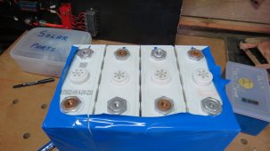
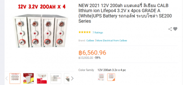
IMG_2414.JPGMain Battery Image.pngSecond Battery Image.pngThai details.pngEnglish details.png
 
Last edited:
Due to a failure on Ali Express my order for 4-New 200Ah cells where lost. I had been waiting for these cells for 2-months, as a result I ordered from a seller in Bangkok 4- 200Ah CALB clone cells. The reason for selecting these cells was the very low resistance.

The cells arrived and I tested them for voltage and battery resistance. The cells wired in series showed a voltage of 12.86 volts, resistance was difficult to obtain.
I decided to start charging them to 13.4 volts which should take the battery to 99%. At that point I would then reconfigure them into parallel and let them balance out.
a few thoughts...
good thing you only charged to 13.4, that means there is a really good chance you did not have a runaway cell.

1) where/what is your BMS? it is your last line of defense, and a smart one can provide insight into what is going on
NEVER (ok, thats a bit strong, how about unless you are a crazy risk taker with your batteries, use a bms), how about, it is strongly advised to NOT put unbalanced cells in series and then "charge them up"; great way to kill your cells unless you have a charger that has balance leads on each cell to make sure you do not kill it.
2) you need to follow a very specific process to safely "top balance" your cells. You cannot just put them in series, charge up to a high voltage, then put them in parallel and hope they balance...not going to work unless you plan on waiting for several weeks (you need a BMS for protection and to help watch the cells).
3) you say you "top balanced" your batteries, from your description I cannot really tell if that happened. You need to "charge" them to the 3.6 range all in parallel, you cannot just hook them in parallel and let them sit. with lifepo4 batteries you really cannot use voltage to tell much of anything EXCEPT at the 3.6v top and the 2.5V bottom..basically you know they are full or empty, everything else is an error prone guess.
4)when you test capacity what tester did you use? are you monitoring EACH cell or just pack voltage? if you do not want to use a bms you can use something like an isdt battgo battery meter to keep an eye on each cell. what was your low voltage cut-off for your capacity test?

it could still be nothing more than a lack of full charge and a unclear use of your testing methodology.
do a full charge to each cell is at 3.6V
configure in series (or test each cell all by itself)
when doing capacity limit testing, you will be taking the cells to a very low voltage; 2.6V; thats a 4S voltage of just 10.4V.

while venders tend to be "very" imaginative when describing their battery capacity, getting 138Ah instead of around 200Ah does mean something is most definitely wrong...but it is too early to tell if its a battery issue, wiring issue, testing issue, or process related.

carefully go thru your steps, consider testing each battery seperately to make it easy.
 
That’s excellent advice, only thing I would add is to verify the capacity tester. Many have had erroneous voltage or capacity readings on theirs. If it’s the kind with a single pair of wires to the battery, for sensing and load those have issues. The new version has separate wires which is more accurate
 
Things have gone from bad to really bad.
I set the cells up in a series configuration and connected one of my desktop chargers cables the + and - terminals on the batter then plugged them into my Brand New 3010P charger and boom. The unit was not plugged in to AC voltage and the unit was not on. I had used this charger just one time previously to charge the cells along with a 30volt 5Amp charger that I have and all worked well. My new desktop unit has some real electical issues I opened it up and two of the 2200 farad electrolitic capacitors are blown up and what else ?????
I just am a total loss now of what to do as I am now down to just the one charger 30volt 5amps and I do not want to blow it up as well.
I checked the configuration several times and it is in my mind it is wired correctly however there seems to be high amperage coming from the battery when the leads are connected. Thoughts please.
 
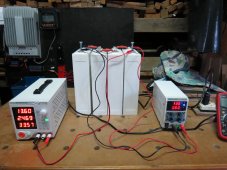
Here is an image with both chargers charging the battery! Please not I was charging at 13.4 volts but as the battery got full the amperage reduced I ten increased the voltage to 13.6 volts to supply extra voltage. There was no BMS on the unit and I manually shut down the power supplies as soon as the voltage within the battery reach 13.4 volts.

IMG_2430.JPG
 
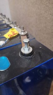
WHOA! Test leads and high-resistance countersunk woodscrews for charging terminals? - yeah. not good.

Try this: with your multimeter, measure the voltage right at the output of one of those supplies.

Now, measure the voltage off the top of the countersunk woodscrew tops. Any difference?

Slow down a little. I'd watch Will's video again, but with better connections. AND, with no bms I'd suggest putting them in parallel to do the parallel balance first.

It's exciting I know, but slow down bro, we've all been there too. :)
 
Using small gauge wires, alligator clips, charging batteries connected in series without BMS; that is not good idea at all.
 
WHOA! Test leads and high-resistance countersunk woodscrews for charging terminals? - yeah. not good.

WHOA! they aren't countersunk wood screws but M8 studs with their head still attached :)

Sorry to read about your power supply.

I fried one a few weeks back with similar setup.
Went from 4 volt charge (1 cell) to 8 volt, 2 cells.
Magic smoke.

If the voltage of the cells are significantly higher then the battery, you will blow up the charger.

It doesn't matter if it's turned on or not.

Happy you still have your 5A!
Should be enough.

In PM we discussed the need of BMS when charging all 4 in series, just as the need for good contact during charge, for all terminals.

Better to have them in parallel, as it's more easy to control the voltage.

You can set to 4v on your 5A charger, by the time you see it decreases you are getting closer to saturation, aka fully charged.

Just don't leave it like that for a night and check regularly (every 30; minutes or so, after you measure +3.450 volt, under 3.450, every hour is sufficient)

For capacity test, each cell individually, if you find this step neseserry.
With 200Ah cells 190-210Ah is expected outcome.

You can measure the internal resistance, and they seem to be OK.
The chance that a cell is faulty is really slim.

Remember the hassles you now are having with the top charge?
You will have it again...
Now for all 4 cells not from half full, but empty.

In theory you can connect everything discharged, and the charge (especially with 5A) should go really equal to full, 3.65v

Personally I do want to have the cells fully charged before I start using them.
This is personal preference.

You can hook it all up to BMS, solar and Inverter, it will take some time before all is fully charged that way.
 
Crocodile clips are OK for charging and discharging.

Ok. Not the best, totally agreed.

Best would be lugs with the following steps:
Clean the terminal, remove oxidation, apply antioxidation compound.
Clean the lugs, remove oxidation, apply antioxidation compound.

Tightening the nut with +4Nm and stay below 7Nm.

The lugs will have matching cables to handle their amperage.

Oh wait..
They already have :)*

People....
10A and 5A.... That is thin wire!!
Not 75A..

Crocodile clamps won't give the best contact, lugs will.
Absolute Downside: the threads!!
They are, as many have found out, weak!

Every difference in the setup using screws will wear out the threads.
Every time this can be prevented is a win.

And yes, the crocodile clamp might have higher resistance then a lug, less efficient.

For the rest of the setup, crocodile clamp is highly advicable.

For speed of charging..
Lugs are, with 5-10% faster charge time.

Don't bash Al, help him!

We know there where a few beginner issues, it's been said.
No need to rub it in or to shout it's stupid.
You might end up looking stupid for shouting...
And it doesn't help anyone
 
Back to the original post.

Your capacity test.
What did you do wrong?

A few things:
Batteries charging in series without BMS. This is not advisable as the BMS is there exactly for that purpose. New cells might be more out of balance then you expect and when one cell is still at 3.35, other might be/ over 3.65.
Your total voltage shows 13.4, but individual cells can be way off.

When charging in series, charge till the BMS stops, one (or more) cell reached 3.65v
Top up the individual cells to 3.65v
When all the 4 cells are 3.65v your battery is fully charged.

Capacity test.
You set your low voltage to 12v.
This suggests that you test in series, not individual cells.

Best to test individual, as there might be huge difference between them, who might be reason for warranty.

12v isn't empty!
For my 48 X 152Ah test, I charged all cells to 3.65v. let them rest (as I can't test 48 cells in one day) and top up before testing to 3.65.
Usually that tool about 10 minutes, like half Ah or so.

My discharge setting was 10A, and 2.2v as low setting.
I let it discharge to 2.2v, rest for several hours (voltage creeps up to +2.8v) and test again. Usually 1 to 2 Ah extra.
After the second run the battery recovers to 2.5v

That is the good way to test and get actual results that you can use.

It's not one 12v battery, it's 4* 3.2v batteries and should be tested as 4 individual units.

If it where 4 X 12v lead acid batteries, you probably would test them as 12v and not 48v.....

The voltages, you went wrong there.
Measure is fun, that's all.
It doesn't tell sh?t.
2.5 is empty, 3.65 is full.
3v is more empty then full.
And probably around 20%. Probably.
Can be 15 or 30%
3.3 is more full then empty, and probably around 70%
Can be 55, can be 85%
Depending on temperature, rest or active state, and how long this voltage holds, + historical readings from that cell....

3.4 isn't 99% Charged.
If it's on the charger, it is between 70 and 90%

The 138Ah, looking at the stop voltage of 12v, roughly 20% left in rest, but this wasn't rest, it was during discharge.
Probably 30%.
138 + 30% of 200Ah is 198Ah.

This calculation is just indication as voltage measurement is so inaccurate.
Except full 3.65 and empty 2.5, it's only indication, rough estimate.

For the people who think the voltages from the BMS, 2.5 and 3.65 are the absolute stress points...
Sorry, you need to study more.

LiFePO4 have safe voltage range of 2.0 (empty) and 4.2 (overcharged)
Charge with or at 4.2 isn't bad at all.
You should not keep the cell at 4.2v
A few minutes is OK, a night... You are in trouble.
Fast charge, high capacity and reach 4.2, you are OK.
Charge with low capacity and keep slowly pushing beyond 3.65 up to 4.2?
You are also in trouble.

Most BMS stop around 3.65, several Daly at 3.75.
Most BMS stop at 2.5, several Daly at 2.25v
Reason?
There is almost no capacity difference between 2 and 2.5v,
Little above 3.65.
So why not stop there, to be on the safe side??
As that's what a BMS is: safety

That doesn't make go beyond those ranges wrong.
You just need to know you are going beyond the safety zone.

What did you do right?

A lot!!

You measured regular the Voltage.
While it's just an indication, it's all we have so better make sure you know it.

The setup:
Busbar, screws that came with the cells. Probably a lot better measure then the EVE cells, as these thermals are factory made with threads and a reinforcemet nut at the base of the terminal to assist in tight mount.
Also M8 that has more "grip"

You used studs.
Kind of.
They still had the head on :)
Perhaps with your cells less critical, but for Eve, absolutely critical if you change the setup a few times, studs!
Not the free screws.

Joining this forum and asking for assistance :)
That's a big thing.

Most of us have been there (I have) as it's quite an expensive purchase and are afraid they are fragile like thin glass.

Every spark, twisting the nuts charging, leaving the babies alone for a while during charge as real life needs you will make you anxious.

While it's not as robust as lead acid, it's not glass either.
They don't break that easy.

Things that can / will damage them is charging without BMS or too long at to high voltage/capacity.
If your charger can't switch from CC to CV and keeps pushing 10A, you will fry the cells even at 3.5v charge.

In other words the right equipment for the right job.

That, you did good also!
Got 2 CC/CV chargers with variable voltage.

So most steps are great!

The rest... Learning curve
 
Last edited:
I agree with all posts.

stop charging without the BMS.

disassemble all cells.

Measure the voltage at the terminals, not at any screws... of each individual cell, and write it down.

Report back here with results.
 
I can understand why people are curious about the odd bolt Al used.

As per my advice...

We can all agree that studs are better then the standard small bolts delivered with the cells.
Even if they are correct length, when tighting them, the twisting motion and force is harsh for the weak threads, and reconfiguration require to unscrew.

Al lives in Thailand, the wonderful country where things aren't available.
Like studs.

The best way to obtain them is to use bolts and cut of the head.

In the past I have used them with head, as a stud.
1622092298980.jpg

Beautiful stainless steel studs in the background.
Sadly.. 3-4 weeks delivery time.

And as I didn't want to wait that long, I used M6 bolts with the nut already screwed in.

The bolt act like a stud, and the nut..
As nut :)
With extra benefit to hold the bolt when tighting.

You can't add lugs later on, but for temporary, it's a better fix then the useless screws most sellers ship with the Eve cells.

In a later stage I did cut off the head, and used as real stud, just doesn't have hex hole on the top.

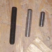
My Franken collection of obtained studs:
1622092883326_edit_3273837272795761.jpg

While there is better and best and worse...
Obtainable is always best.

And it does leave room for improvement, agreed.
If you can't get, you can't improve.

And how bad is it??
Carbon steel studs aren't advicable, with Loctite red they won't give a trouble in the aluminium terminals (no galvanic corrosion)
The copper bus-bars are tinned / electroplated, and the stainless steel washers and bolts won't have a problem.

Is it worth the risk of ripping out the thread to replace them with stainless?
Absolutely not.

The chance that this combination will become a problem due galvanic corrosion or is a problem due slightly higher resistance in the stud is minimal.

I can't advice to use this mix, unless it's all you can get.

Welcome to Thailand :)
 
Last edited:
I can understand why people are curious about the odd bolt Al used.

As my advice...

We can all agree that studs are better then the standard small bolts delivered with the cells.
Even if they are correct length, when tighting them, the twisting motion and force is harsh for the weak threads, and reconfiguration require to unscrew.

Al lives in Thailand, the wonderful country where things aren't available.
Like studs.

The best way to obtain them is to use bolts and cut of the head.

In the past I have used them with head, as a stud.
View attachment 50623

Beautiful stainless steel studs in the background.
Sadly.. 3-4 weeks delivery time.

And as I didn't want to wait that long, I used M6 bolts with the nut already screwed in.

The bolt act like a stud, and the nut..
As nut :)
With extra benefit to hold the bolt when tighting.

You can't add lugs later on, but for temporary, it's a better fix then the useless screws most sellers ship with the Eve cells.
You could cut the heads off, and cut a slot in the end to hold it...
 
You could cut the heads off, and cut a slot in the end to hold it...
:)
That's what I advised Al, to cut the head.

With Loctite red (please do use primer as aluminium and stainless steel need to get activated) holding it isn't needed.

I like to put 2 nuts on the top, and twist it that way into the terminal.
Then untighten the 2 nuts, and screw one down so it give some slight pulling force on the Loctite red.
When all set, screw off the 2 nuts.

This way the thread of the home made stud is good to get a new nut on during assembly.

In my experience... The cutted side isn't always so easy to get the nut on the first few times.
Adding a slot probably would make that worse.

Al could find galvanised bolts, the cutted edge will have no protection.

I advised to have the cut side on top, so the bare iron doesn't touch the aluminium.
 
Here is an image with both chargers charging the battery! Please not I was charging at 13.4 volts but as the battery got full the amperage reduced I ten increased the voltage to 13.6 volts to supply extra voltage. There was no BMS on the unit and I manually shut down the power supplies as soon as the voltage within the battery reach 13.4 volts.

View attachment 50599
I don't see a BMS, and you are charging in series.

Experienced people are telling you not to do that, you might want to pay attention.
Ignore the advice, and you usually wind up needing to buy new cells.

Someone recommended an isdt batgo monitor, be warned, it is not a BMS. A real BMS will disconnect when cell voltages would damage the cell, that device will only tell you about it. We have had a user here make that mistake (quite vocally). On my 280AH cells, it takes approximately 2 amp hours worth of current to go from 3.4v to 3.65v. Depending on your charger, that could be just a few minutes. Lots of examples here of people that "watch it like a hawk" that ballooned their cells.
 
Thank you everyone or all of your efforts.
Please let me clarify some issues raised, regarding the use of studs versus bolts they are all Stainless steel bolts
and for ease I continued to use them even through I had cut longer Stainless steel studs to be attached to the terminals at
a point when the BMS is attached again.
Regarding charging the battery pack and not using a BMS it was advised that one could do that if they constantly monitor the voltage of the batter and cells. This I did over a period of about 18 hours. Little to no sleep there?
When the cells where shut down by the BMS after discharging to 12 Volts of 3.0 Volts per cell, I simple connected them in parallel and within a short time they had achieved balance.
The voltage of each cell at this time was Cell#1 @ 2.961 volts, Cell#2 @ 2.961 volts, Cell#2 @ 2.961 volts, Cell#2 @ 2.961 volts

I have spent many months and viewed many video's regarding the building and configuring of a LiFePo4 battery and have found that there are many options and methods of supposedly getting this done.
What I would appreciate is one person to volunteer their time to slowly walk through the process, I will do EXACTLY as instructed.
I however an a old retired person and I need clear instructions that stay on course. If you have the time and interest in assisting me please let me know and we can chat using the chat channel here.
 
Hi Al,

I've tried to provide some guidance, but better someone else take it from here.

It seems hard for you to understand that voltage doesn't match state of charge.
4 X 2.961 isn't 4 X 18% SOC.
Somewhere between 15 and 21% roughly.
Keeping them parallel would take weeks to get them all at 18% as there is little to no voltage difference.

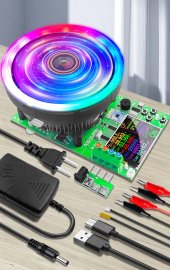
IMG_20210527_153423.jpg

Capacity testers like this are used for single cell or cells in parallel.

I would not use series to do capacity test, if I need to, I'll set the BMS to same low voltage as the tester.
(2.2-2.5v per cell, so 9-10v)

It will not give as accurate results as per cell testing, but will go faster.

Will does mention in his top Balance and charge profile sticky that it is possible, not advised, to do without BMS, for experienced users only.

While I like to help, choosing routes like this, makes it hard for me.
It's a leaning curve and took me long enough with way to much additional costs.

Probably because I'm just as thickheaded... 555
And eternal an optimist that keeps going.

Due my medication use (morpine based) concentration is often an issue, good combo to make almost all mistakes possible :)

Looks like your getting just as good at it as I am.

@Supervstech , can you guide Al?
Your'e good in providing clear step by step instructions and ask to report back
 
Thank you Frank for all of your assistance.
I had sent to you information on the private forum chat we have had but you may not have viewed it.
If you see this, please view what I sent you.
It seems that no one is interested in assisting me so I guess I will just have to go it alone.
 
Because of the difficulty and seemingly low capacity on these used cells I would tend to run the assembled battery up to the max 3.65 vpc and take it all the way down to the minimum 2.50 vpc in the capacity test. At that point they are what they are.
 
Back
Top