diy solar

diy solar

Impress your friends by using correct units and abbreviations

Power factor only applies to AC. There is no phase on DC, only on AC.

Hence VA = W on the DC side.


While using watts and watt hours is good for making assessment for sizing system generation and storage capacity, VA (and reactive power) is something you need to be very aware of especially if you are powering large inductive loads such as motors.

You can find your inverter would appear to have sufficient rated capacity, when for an inductive load it may not.
I will add that thought to my loading projects. Up until now, it has been DC power supplies powered by an inverter and then either electronic loads or passive loads hooked up to the DC power supplies. I will have to rummage around and see how many single phase motors we have laying around, even if I don't push the inverter, I can still measure differences
Power factor only applies to AC. There is no phase on DC, only on AC.

Hence VA = W on the DC side.


While using watts and watt hours is good for making assessment for sizing system generation and storage capacity, VA (and reactive power) is something you need to be very aware of especially if you are powering large inductive loads such as motors.

You can find your inverter would appear to have sufficient rated capacity, when for an inductive load it may not.
I'll add motors to my loading considerations. Watt hours still screw with my head. I can understand the grade school explanations....if you have a 100 watt light bulb and you get charged 10 cents per kilowatt hour it cost you dime for for 10 hours....or not...chances are I did not get that right....hence my problems figuring it all out.
 
Power factor only applies to AC. There is no phase on DC, only on AC.

Hence VA = W on the DC side.

DC from battery to inverter carries AC ripple, current looks like rectified sine wave. It is quite large at full load.
My projection at full load (I only measured at 40% load) is that heating of wires and fuses from that RMS current is equivalent to current 111% of mean current. So I say to size fuses another 12% higher, after applying the usual factors of minimum voltage, inverter inefficiency, 25% headroom.
 
Found this regarding VA compared to Watts (similar to what has been discussed here already):

“A device could consume only 1000w for example, but it's apparent power could be 1200va. In an ac circuit current goes back and fourth, that extra 200w (reactive power) is basically being shuffled back and fourth between load and power source.

While it isn't being consumed by the load it's still placing demand on the circuit. The higher the reactive power the worse the power factor is. If real power and apparent power are equal you have a power factor of 1, an ideal situation where voltage and current are perfectly in phase.

That's why people call it imaginary power because it isn't actually being used. The reason it can be important is if you are running devices with a poor power factor then they will place a larger demand on your inverter for the same amount of power, because even though the reactive power isn't getting used it still needs to be supplied by the power source.”

From:

 
Last edited:
Furthermore (not trying to gild the lily):


“With inductive loads the load itself reacts with the power source. With each cycle of current a magnetic field is set up within the motor coil windings. As the magnetic field starts up there is an inrush of current, once the field is established nothing much happens, and then at the end of the cycle there is an outrush of current. The effect has a time lag and the outrush of current fights the incoming current for the next cycle and thus reduces the total amount of power available to do the work. This effect is called Power Factor and can be defined as the ratio of the real power absorbed by the load and available to do work to the apparent power flowing in the circuit. With a typical inductive load the Power Factor might be in the region of 0.8…

…That's why you will see inverter manufacturers quote their rated output in VA - its because it is the higher number and so looks better on the spec sheet. Everybody does it. If your inverter is running a toaster or a coffee maker it doesn't matter but if you are running a vacuum cleaner or power tools it does and you need to be looking at the Watts {?} figure…

The rated output for our most popular inverter charger, the Victron MultiPlus 12/3000 is 3000 VA but for inductive loads it is rated at 2400 Watts. This represents a Power Factor of 0.8 since 3000 VA x 0.8 = 2400 Watts”
KVA-Watts.jpg
 
The rated output for our most popular inverter charger, the Victron MultiPlus 12/3000 is 3000 VA but for inductive loads it is rated at 2400 Watts. This represents a Power Factor of 0.8 since 3000 VA x 0.8 = 2400 Watts”

When running at maximum, outputting 2400W, is it pulling 3000W from the battery?
The pictured foam is labelled “wasted electricity”, is that 600W?
If so, why isn’t this reflected in an inverters efficiency… 1 / (3000/2400)?
(80%)
 
When running at maximum, outputting 2400W, is it pulling 3000W from the battery?
The pictured foam is labelled “wasted electricity”, is that 600W?
If so, why isn’t this reflected in an inverters efficiency… 1 / (3000/2400)?
(80%)
Reactive power is power reflected back into the inverter.
That can have several different effects depending on the inverter topology.

If the inverter is fully bi-directional, in other words, real ac power fed back synchronously into the output, can quite literally charge the battery, then there is no real problem. The inverter will handle reactive power easily. Provided of course its capable of working safely at that power level.

The problem arises with inverters that are not fully bi directional. Reflected power coming back in, has nowhere to go, and usually results in a destructive over voltage or over current, which can easily let the smoke out.
Many of the cheaper cheaper high frequency inverters are like that.

Anyhow, a good robust bi directional inverter seeing a 3000 VA reactive load, with only 2400 watts of it being resistive, will only theoretically draw 2400 watts from the battery, assuming the inverter has an impossibly high 100 percent efficiency.
There will however be 3000 watts worth of constantly circulating power in the wiring, mosfets, transformer, the heatsink, and all the power handling parts.

Those must be rated for the full reactive circulating energy, even though only 2400 watts (theoretical) has to come from the battery to supply the 2400 resistive power in the load. Again assuming 100% theoretical power conversion efficiency.
 
If the inverter is fully bi-directional, in other words, real ac power fed back synchronously into the output, can quite literally charge the battery,
So the "foam" in the pic gets pumped back into the barrel?
And if this were the case, is it "wasted electricity" (as labeled), or does it get reused?
 
So the "foam" in the pic gets pumped back into the barrel?
And if this were the case, is it "wasted electricity" (as labeled), or does it get reused?
in a fully bidirectional mode, the foam is pumped back into the barrel, charging the battery.

wiring (resistive) losses are turned into heat either direction
 
Wasted power, current shoved back the way it came (out of phase) hopefully either charges capacitors or charges battery. Recovering most energy except I^2R losses. But could get burned up as heat in semiconductors which would be bad. I'm not clear on all the inverter architectures, how some behave. When I've designed linear analog amplifiers I put in diodes to clamp voltage, hoping to protect from inductive kick.

Capacitors in inverter can only store the current used for a fraction of a millisecond, smoothing out high frequency switching. They aren't nearly large enough to deal with 60 Hz.

If poor power factor is due to rectifier/capacitor front end like my VFD, current will be in phase with voltage (power delivered to load, never stuffed back into inverter), but current waveform is not a sine wave. The I^2R power lost in wire and transistor resistance is increased.

If poor power factor is due to inductance of a transformer, it is 90 degrees out of phase with voltage and nearly 100% gets stuffed back into inverter (except for what was lost due to resistance.) But a small number, just a few watts, which you and the inverter can live with.

I think in the case of a motor, significant energy is stored in rotating mass, or when elevator comes back down in "potential energy" due to gravity. That could be a large amount stuffed back into the inverter.

Some interesting waveforms. Green trace is AC current, red is ripple (AC component) of battery current.

 
So the "foam" in the pic gets pumped back into the barrel?
And if this were the case, is it "wasted electricity" (as labeled), or does it get reused?
Both actually.

Think about a capacitor connected across an ac source.
On the rising part of the positive half cycle it requires current to charge it up.
On the falling half of the positive half cycle, the current reverses to discharge the capacitor.
Same again on the negative half cycle.

Current is flowing in and out of the capacitor, the source has to produce that, which takes some effort.

You could really load up your inverter doing something like that, and it would be working very hard doing nothing useful.
The current cycles back and forth and does not need to come from the battery in a perfect 100% efficient world.

Our 100% efficient bi directional inverter, takes the reflected incoming current, stores it on the dc supply rail (in another capacitor) then pushes the same current back out again in the opposite direction. All jolly good fun, but a real inverter has to work hard to do it.

Round and round went the ruddy great wheel.
All froth and bubbles, but no beer.
 
Last edited:
I'm not clear on all the inverter architectures
I’m not aware or wasn’t aware of a lot of things I learn here. I say I’m good with electrical things but I’m certainly not well versed.
If I was in college to become an EE I’d want you for a professor LOL. I understand your dissertations and have learned a lot here.
I appreciate your posts and thoughtful overviews of the parameters that are deeper than yes/no answers. Not to leave others out- just highlighting this moment. Thank you all.
So the "foam" in the pic gets pumped back into the barrel?
And if this were the case, is it "wasted electricity" (as labeled), or does it get reused?
My understanding is that it gets reused but not usually to do “work” so in a simplistic sense notwithstanding the excellent postings here I think in general that is why it is considered “waste.”

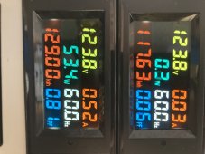
My guerrilla GTI runs through a meter so I can track contribution of its measly 200W of panels. The power factor is a bit fascinating to me because there’s no load on that circuit when the sun’s out. I imagine that is the net effect of it balancing output to match the grid? Dunno image.jpg
Good learning things here
 
The power factor is a bit fascinating to me because there’s no load on that circuit when the sun’s out.
It can't really calculate PF when the current is zero. PF is calculated as the cosine of the phase angle between current and voltage.

All this talk of power factor gets a bit muddy when one considers all of the switching power supplies in use these days. They use PWM to control voltage, so they don't look anything like a resistive load. They look more like a hit 'n' miss engine, only taking power when they need it to keep the output running smoothly.

Watching the current with a current transformer is rather eye-opening. I didn't measure line voltage here, so I don't know the power factor, but you can clearly see that current is not the happy little sine wave we learned in school using just resistors, capacitors, and inductors. Here is an example of my oscilloscope watching itself use power:

ds0007-jpg.83488


More examples are shown in a previous post:

https://diysolarforum.com/threads/current-transformers-a-quick-look.35258/
 
It can't really calculate PF when the current is zero. PF is calculated as the cosine of the phase angle between current and voltage
Thanks. There is current:)
I said “no load” but technically the grid connection is a load and it is ‘pushing’ a smidgeon higher voltage than the grid is presenting. Probably should have phrased differently because yes- there certainly is current. 1.4A at the moment. By load meaning the AIO isn’t taking any power other than its self-check of .3W (usually 0.2W).
 
My grid-tied inverter is designed to inject increasing amounts of reactive power as grid voltages climb high. It's a standard required for GT inverters here since December 2021. When I invoked this capability it made a big improvement with our grid over voltage problems.
 
I have this suspicion that when electrical grid operators say "Reactive Power" they aren't talking about the electrical engineering terms "Inductive Reactance" or "Capacitive Reactance".


Seems to be more like "Reacting to over-voltage or under-voltage condition."
Nothing to do with leading or lagging current, which power-factor correction can address (e.g. switched capacitor banks.)

My grid-tied inverter is designed to inject increasing amounts of reactive power as grid voltages climb high. It's a standard required for GT inverters here since December 2021. When I invoked this capability it made a big improvement with our grid over voltage problems.

As voltage climbs, it injects even more power? I'd think that would drive voltage even higher.


"... including overvoltage which requires reactive power absorption."
 
As voltage climbs, it injects even more power? I'd think that would drive voltage even higher.
Not real power. The reactive component of production increases. It made a big difference with my over voltage problems.

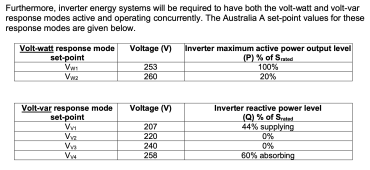
We have two modes which apply when grid voltage climbs above the first set point (253 V):
- volt-watt mode
- volt-var mode

These are the new set point standards:

Screen Shot 2022-11-22 at 3.27.19 pm.png
Generally it's a linear adjustment between set points.
 
Last edited:
Back
Top