diy solar

diy solar

Installing Sterling B2B - grounding question

MEN!

New Member
Joined
Jul 7, 2020
Messages
61
Hi guys,

Looking to install a Sterling BB1260 in my Sprinter van. My house battery bank is made up for (2) 200Ah 12V LiFePO4 in parallel for a 400Ah 12V bank. This bank is a floating system, nothing is grounded to the vehicle chassis. All of the electrical devices connect to my pos and neg bus bars.

It would appear from my internet reading that charging this type of ungrounded house system from the vehicle alternator/starter battery is a no-no. Would you guys agree? The Sterling will be connected to the Starter battery rather than directly to the alternator...does this make difference? Would I be okay leaving my house system isolated? If not.is my solution to simply run a wire from the house neg bus bar to an appropriate grounding point on the vehicle chassis?

If all the above is true, what gauge should I use considering the size of my bank? There's really no convenient place to run the ground wire to the chassis..my batteries are located inside the Sprinter all the way in the rear.

Thanks very much for any help
 
Last edited:
The sprinter starter battery negative is connected to the vehicle body, there is no separate chassis as such, all van metal is connected by welding.

The Sterling battery to battery charger does not fully isolate the output, thus the negative connection on the unit is common to both the starter and house battery. Thus like it or not, once you wire up the Sterling unit the house batteries negative are connected to van metal.

The Sterling unit connected to the engine starter battery will be also connected to the alternator by a suitable length of MB cable between battery and alternator.

With the batteries at the rear, ideally you need to mount the Sterling unit as near as practical to the batteries, this will need a long cable to the starter battery with a suitable fuse at the starter battery, A 100A Mega link fuse and 16mm2 or better 25mm2 cable.
To save running a negative cable to the starter battery, connect the Sterling negative to your negative buss bar and a 25mm2 cable from the buss bar to the van metal. Use a substantial bolt and clean paint from the contact area. Useful points are the load bay tie down points.
If you are unsure of your skill making a reliable connection to the van metal, run a cable ( 16mm2/25mm2) from the the engine battery negative to the Sterling unit. Although this the the recommended method by Sterling, using the van body is a practical alternative.

The fuse at the house battery ideally should be a class T fuse but with a 12v system a MRBF fuse is OK.

If anything is not clear make a comment and I will try to respond.

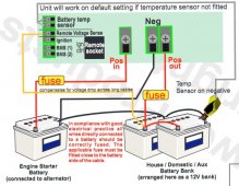
Note if you use the van metal as the earth connection, the two cables shown in the Sterling diagram from the starter battery to the house battery and neg connection on the unit are not required. The starter battery is connected to van metal with MB cable. The negative path in completed when you wire the Sterling neg to the house negative buss bar, that in turn is wired to van metal.

If you intend fitting a permantly installed inverter in the van there are safety implications. A correctly installed systen with protective circuits are needed. You may need advice in this area.


sterling.jpg
Mike
 
The sprinter starter battery negative is connected to the vehicle body, there is no separate chassis as such, all van metal is connected by welding.

The Sterling battery to battery charger does not fully isolate the output, thus the negative connection on the unit is common to both the starter and house battery. Thus like it or not, once you wire up the Sterling unit the house batteries negative are connected to van metal.

The Sterling unit connected to the engine starter battery will be also connected to the alternator by a suitable length of MB cable between battery and alternator.

With the batteries at the rear, ideally you need to mount the Sterling unit as near as practical to the batteries, this will need a long cable to the starter battery with a suitable fuse at the starter battery, A 100A Mega link fuse and 16mm2 or better 25mm2 cable.
To save running a negative cable to the starter battery, connect the Sterling negative to your negative buss bar and a 25mm2 cable from the buss bar to the van metal. Use a substantial bolt and clean paint from the contact area. Useful points are the load bay tie down points.
If you are unsure of your skill making a reliable connection to the van metal, run a cable ( 16mm2/25mm2) from the the engine battery negative to the Sterling unit. Although this the the recommended method by Sterling, using the van body is a practical alternative.

The fuse at the house battery ideally should be a class T fuse but with a 12v system a MRBF fuse is OK.

If anything is not clear make a comment and I will try to respond.

Note if you use the van metal as the earth connection, the two cables shown in the Sterling diagram from the starter battery to the house battery and neg connection on the unit are not required. The starter battery is connected to van metal with MB cable. The negative path in completed when you wire the Sterling neg to the house negative buss bar, that in turn is wired to van metal.

If you intend fitting a permantly installed inverter in the van there are safety implications. A correctly installed systen with protective circuits are needed. You may need advice in this area.


View attachment 54237
Mike
Mike,

Thanks for your advice. I do have a couple questions.

I would feel better about foregoing the ground (For my 12v system) and running a wire from starter battery neg to house battery neg. Buying the extra wire does not bother me. To be clear..will it be an issue if i run the starter battery neg to the house neg bus bar and not the actual battery itself?

Also, I do have 3000watt inverter already installed. What potential issues can arise from this if any?

Thanks again
 
  • Like
Reactions: Sea
will it be an issue if i run the starter battery neg to the house neg bus bar and not the actual battery itself?
That will not be an issue, the 'neg' on the Sterling will need to be connected to the buss bar. Note that in effect you house battery system will be not be floating as it will be connected to chassis via the starter battery negative van connection.
To comply with regulations and safe practice, the inverter, if permanently installed and connected to multiple outlets and appliances, must feed the AC circuit via a double pole RCD or RCBO. In addition the inverter must be a type with a neutral to earth bond inside the inverter or have the facility to do so. In addition the case of the inverter muse be connected to van metal, as must the protective earth of the van AC circuit. When you have shore power its necessary the inverter and its neutral bond is isolated. If the inverter is a Victron Muliplus or a similar type, then the neutral bond aspect is taken care of by the unit. RCD and MCB double pole protection (or RCBO) is still needed after the shore power inlet and at the Mulitplus output.

Mike
Mike,

The sterling instructions say to run the sterling neg to starter battery Neg. Are you suggesting I only run the sterling neg to house neg bus bar instead? And would you mind telling me why the departure?

thanks
 
Last edited:
The sterling instructions say to run the sterling neg to starter battery Neg. Are you suggesting I only run the sterling neg to house neg bus bar instead? And would you mind telling me why the departure?
Point one is that the positive and negative buss bars are the connection points for the 'big' 400Ah battery.
I assume the B to B is mounted near the house batteries, You have a quite thick long cable from the negative buss bar to the engine battery negative. ( if not using van metal for this path). Electrically connecting the Sterling 'neg' to the negative buss bar results in a slightly longer electrical path to the engine battery compared to running an additional cable. This will make no significant difference to the Sterling unit regarding power taken from the engine battery.
In fact its technically slightly better having a short connection between the Sterling unit the house battery. All battery voltage monitoring in the Sterling unit will be based on the service battery voltages, so having the shortest path in the cables will be an advantage.

One final point, the Sterling products were originally designed for the marine market ( mostly GRP with no chassis/metal body) and the connection diagrams have evolved from that.

Mike
 
Back
Top