diy solar

diy solar

Interconnect wire gauge question

NMNeil

Solar Enthusiast
Joined
Mar 14, 2020
Messages
443
One for the amperage capacity gurus.
I have 32, 100ah cells and will connect two in parallel via an aluminum bus bar to give the equivalent of a single 200ah cell. The welded studs on the cells are only 4mm, so the plan is to drill the center of the bus bar and have a bolt as the actual electrical connector. These bolts would then connect the other cells in series via connecting wires and crimp/soldered terminals to give me 48 volts.
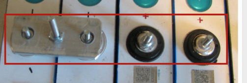
This is my proof of concept. I've drilled the outer holes to 8mm which means the bus bar rests on the largest contact area of the cell terminal.
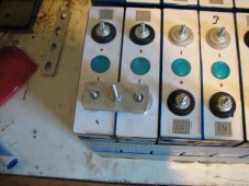
IMG_2676.JPG

The book of words for the MPP all in one unit specifies a maximum current draw of 83A @ 48V, so my question is, what would be the best bolt and AWG size for the interconnecting wires for that amperage?
 
I've drilled the outer holes to 8mm which means the bus bar rests on the largest contact area of the cell terminal.
That looks like a good design. Why not put a set of similar bus bars on top of these between the pairs for serial connections?

And/or, if you use the center bolt and nut, I would try to avoid having the nut be the contact area. I understand you want to attach the bolt but i think you'd be sacrificing all the aluminum contact area.
Screen Shot 2021-07-15 at 10.11.01 AM.png

And why not make bus bars with your enlarged 8mm holes (good design) that span 4 cells?
Screen Shot 2021-07-15 at 10.18.29 AM.png
 
I tried that, in fact one of the bars is in the photo. But due to the discrepancies between cells I would have to custom make each one. I also had the fear that if the cells start expanding and contracting it would put a lot of strain on the terminals. Having the cells in pairs means that if I have to change a pair out it would be easy and would not involve making a replacement custom bus bar.
The nut and bolt in the photo is just the proof of concept and I planned on having something slightly larger for the actual build.
I actually got the idea of using cables rather than solid bus bars from a Jehu Garcia video.
 
I also had the fear that if the cells start expanding and contracting it would put a lot of strain on the terminals.
Very true. I think most suggest using more cell compression that a couple wraps of tape. I opted to custom make the bus bars with a bit of slotting to allow for easier installation.

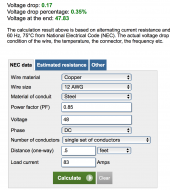
But to answer your question, i ran your numbers thru the voltage drop calculator and its a bit disturbing how small the wire can be. Someone double check this... 12awg only .3% drop on 48V, 83A, .5ft ???

Screen Shot 2021-07-15 at 11.23.53 AM.png

 
And I just happen to have the remains of 500ft rolls of 10AWG in red and black :)
But I will wait for others to chime in as it does seem rather thin.
 
Very true. I think most suggest using more cell compression that a couple wraps of tape. I opted to custom make the bus bars with a bit of slotting to allow for easier installation.

But to answer your question, i ran your numbers thru the voltage drop calculator and its a bit disturbing how small the wire can be. Someone double check this... 12awg only .3% drop on 48V, 83A, .5ft ???

View attachment 56383

Sounds right to me by pure theory, though I'd probably never actually do it to the limit what for not trusting my wiring and terminations to be flawless.

Check 8 awg on that once. That's what I'd use for say, 100a, if it's only a couple inches. But I'd definitely load test and check it with my thermal cam to be sure.

I irritate the sparkies constantly when I'm working on control panels because I'll put in wires which are "not to code" according to them.


The killer for wiring capacity is the total resistance. A shorter wire has less resistance and thus heats up less with a given current.

It kind of makes sense when you check the cross sectional area of these bus bars vs whatever cable you'd think ought to be used.
 
And I just happen to have the remains of 500ft rolls of 10AWG in red and black :)
But I will wait for others to chime in as it does seem rather thin.
You'll know pretty quickly by seeing if the wire gets warm/hot. It "looks" like 10awg will be plenty...
 
Oh look. 4awg with a 20a load that's pretty much the max for my teardrop setup is less than 8mv drop over 3 inches lololol
 
Very true. I think most suggest using more cell compression that a couple wraps of tape. I opted to custom make the bus bars with a bit of slotting to allow for easier installation.
I connected 2 cells in parallel then put 4 of these together to give me a 12 volt 'brick'.
I put blocks of timber at each end then clamped them all together.
The duct tape was then tightly wound round, and when I removed the clamps the cells didn't move.
There's been a lot of discussions regarding clamping cells together to extend their life, and if it's worth it, so this is a bit of a compromise.
 
Back
Top