diy solar

diy solar

Interfacing with Valence built in monitoring

t3chN0Mad

New Member
Joined
Dec 4, 2019
Messages
22
Hey all, first post but I've been lurking about on here and watching lots of Will's videos for a bit. I was able to find a Valance U27-XP locally and decided to try it out. I made up an RS485 cable and downloaded the software and was able to communicate with the battery. I am working on making my own BMS and thought about just getting rid of the onboard communication and hooking up directly to the temp sensors and cell voltage leads. After I got the back off and saw how nice of a job they did with everything, I was hesitant to start chopping wires. So, I started snooping on the RS485 communication and I've figured out it is using the MODBUS protocol at 9600 baud, 1 stop bit, but I couldn't get it to respond to any commands to poll the registers(command 3?) without having the diagnostic software connected. I also get parity errors on what appears to be the commands coming from the diagnostic software. If I have that running and send commands at the same time, then I can get a response. I did some more snooping and found some commands where the diagnostic software is using mark parity, so I think that could be the hang up. Does anyone have any knowledge of MODBUS and any MODBUS programming libraries that would allow me to configure a connection for mark parity?
 
Hey, thanks for the reply. I did a lot more work over the weekend and actually got pretty far. I was able to figure out that the Valence software is sending a command to “wake up” the battery before it does anything else. I’m in the process of validating my work and then I will have more specifics for everyone. My Adafruit board and relay shield should be here within the next day or two and if all goes well I’ll have a POC soon as well.
 
I've been pondering doing something like this with the goal of being able to monitor (or at least log all the batteries in the bank rather than just one at a time.
 
I've been pondering doing something like this with the goal of being able to monitor (or at least log all the batteries in the bank rather than just one at a time.
I’ll have more information available after I get it all organized. It should be a good jumping off point for anyone who wishes to monitor and/or protect these batteries without opening them up. I’ve written some python scripts that I’ll release for people to do simple monitoring. In the near future as I start working on the BMS, I’ll share the code for that as well.
 
Here's a github repo with the work I have done so far and kicking off the actual BMS project. OpenXPBMS
This looks great. Got four batteries and the USB dongle done working with the Valence Diag Software. Looking to now add into my CCGX or another way to latch relays to disconnect the batteries based on the data.
Still doing some of my install - if I find the time, I’m hoping to contribute to your project and effort.
 
Happy New Year! I am pleased to announce a huge update that I just pushed to the OpenXPBMS github repo. There aren't a lot of new lines of code, but it is now able to read cell voltages from ONE battery and log them to an SD card and the serial console. There was a lot of trial and error to get to this point, but I feel like I'm finally over the hump and I expect to keep making commits frequently. The next step is to get the temperature code from the python script ported over and then I'll be ready to write the logic to control the relays. Once I have it fully working with one battery, I will work on implementing functionality for multiple batteries. I'm writing the firmware with that feature in mind, so most of it will be done already, but the tricky part will be dynamically constructing the correct request messages for each battery. I also expect to incorporate a few more pieces of hardware, like an RTC for more accurate data logging and design a PCB to mount all of the different modules to. Please go check it out and let me know what you think. If you would like to contribute to the effort in any way, please contact me. I'm excited to see where this is at in the next few weeks.
 
Hey, another quick update. The code to monitor one battery is done and should be fully functional, but needs testing. It has been uploaded to the github repository. Anyone that would like to test it can contact me if they have questions on what components to use. For the next couple of weeks, I'll be focusing on installing a single U27-12XP battery and the BMS in my van to test with in preparation for a trip, so I'll be focusing on that aspect over development for a bit. Once the current sketch is confirmed stable, I'll continue on with multi battery support and other features.
 
Hey, another quick update. The code to monitor one battery is done and should be fully functional, but needs testing. It has been uploaded to the github repository. Anyone that would like to test it can contact me if they have questions on what components to use. For the next couple of weeks, I'll be focusing on installing a single U27-12XP battery and the BMS in my van to test with in preparation for a trip, so I'll be focusing on that aspect over development for a bit. Once the current sketch is confirmed stable, I'll continue on with multi battery support and other features.
Sent you a PM
 
Quick update:

TLDR: If you haven't sent off for PCBs yet, wait for the next revision. If you have ordered PCBs, don't worry they will work with some tweaking. Software is still in developmental stages; a couple critical bugs are known and logged.


My PCBs arrived of the initial design. I ordered through JLCPCB and am very happy with the quality and turnaround. Everything works, but I did discover a couple of problems which were totally my fault: I routed the traces for the RS485 module backwards. It can be made to work as-is(I got mine working), but I'll be revising the design when I get a chance. Also, the two headers of pins for the the grand central are out of alignment with each other by roughly .5-1mm. Again, the pins can be bent a little and everything will work, but I'll fix this in the next revision as well. Lastly, there are two sets of holes for pins at the bottom of the RS485 module. This was to provide soldering points for the wires going to the AMP connector in line with the pins on the RS485 module. I connected the outer four respectively, but did not put traces on the inner four. The easy fix was just bridge the pins with solder, but I will make sure to include traces in the next revision so that isn't necessary.

In other news, I'm working on a couple critical software fixes. Low temperature cutoff is NOT working correctly at the moment; Additional logic needs to be written to handle negative temps correctly. Also, when it fails to read data from the battery, the relays are remaining on, which is not intended behavior. Both of these have been logged in github. I will update those issues as they are resolved.
 
Hey just looking to see if any progress was made with this endeavor? Not looking to come off as pushy, just curious.
 
I have been building upon the foundation that t3chN0Mad started, and have built my own Raspberry Pi-based monitor for Valence XP U-charge batteries.
It's not perfect, but it works with my 11 modules in series, and probably works with more modules.
I receive SOC, Current, Module voltage, PCB temp, High Temp, Low Temp, High Cell V, Low Cell V of each battery.
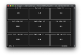
I have also constructed a simple UI for visual monitoring of the data.

I'm using it to control the charge of Valence batteries in my Th!nk City -99 EV, so it's not with Solar panels in mind...
It's a much grittier project than t3chN0Mad's, with an USB-FTDI RS485 dongle and a separate Solid State Relay to end charge when first cell reach my specified voltage.

In the far horizon, I would probably build a complete EV BMS upon this foundation with contactor controls for charge and discharge, to also open contactors when voltage is low, but for now this suits my imminent need.

I leave no guarantees, and have not tested it more than briefly, but feel free to use and continue to build upon it.
I have not documented as pretty as t3chN0Mad's project either, but I think it's quite straight forward.

Included is a printscreen of the UI in action (Ran it on macOS over SSH to my Pi. The script does not work on macOS. It works in Windows if you remove GPIO-functions).
Do not run the software over SSH other than for testing, when the SSH session is terminated, the software is interrupted and stops reading, but the relay remains on.
Skärmavbild 2020-03-03 kl. 12.29.57.png

Here's my repository (the folder RaspbPi contains my script);
 
Last edited:
I have been building upon the foundation that t3chN0Mad started, and have built my own Raspberry Pi-based monitor for Valence XP U-charge batteries.
It's not perfect, but it works with my 11 modules in series, and probably works with more modules.
I receive SOC, Current, Module voltage, PCB temp, High Temp, Low Temp, High Cell V, Low Cell V of each battery.
I have also constructed a simple UI for visual monitoring of the data.

I'm using it to control the charge of Valence batteries in my Th!nk City -99 EV, so it's not with Solar panels in mind...
It's a much grittier project than t3chN0Mad's, with an USB-FTDI RS485 dongle and a separate Solid State Relay to end charge when first cell reach my specified voltage.

In the far horizon, I would probably build a complete EV BMS upon this foundation with contactor controls for charge and discharge, to also open contactors when voltage is low, but for now this suits my imminent need.

I leave no guarantees, and have not tested it more than briefly, but feel free to use and continue to build upon it.
I have not documented as pretty as t3chN0Mad's project either, but I think it's quite straight forward.

Included is a printscreen of the UI in action (Ran it on macOS over SSH to my Pi. The script does not work on macOS. It works in Windows if you remove GPIO-functions).
Do not run the software over SSH other than for testing, when the SSH session is terminated, the software is interrupted and stops reading, but the relay remains on.
View attachment 8423

Here's my repository (the folder RaspbPi contains my script);

Nice work!
 
Back
Top