diy solar

diy solar

Interfacing with Valence built in monitoring

Would it be hard to adapt this to work with a 24v series attached battery bank?
With series arrays you need to find a way to balance each part of the series string. The Valence batteries can do this internally, but it's hard to reverse engineer the serial comms to do this - would need access to the official Valance U-BMS hardware and a serial monitor/interceptor. As far as I know, no-one has done this yet.

Another option is to add some simple balancing hardware across each pair of 12V. This will keep the parts in balance, and then my basic BMS will take care of the rest (intra-cell balancing, voltage/temp monitoring, etc.)
 
Can you elaborate on what the "simple
balancing hardware" would be? What about something like this: https://www.amazon.com/7Series-Prot...y+balancer&qid=1607436582&s=industrial&sr=1-4 ?
See point #13 here:
Where it talks about 2/4-channel balancers
 
Would it be hard to adapt this to work with a 24v series attached battery bank?
No it wouldn't be hard but it won't balance one battery to another so you'll need an aftermarket balancer for that.
One downside about the aftermarket balancer is it does have a residual draw after balancing is complete. I know this because I had 30 batteries in series with a valance brand BMS which was doing a fine job keeping it balanced. I simultaneously put on the aftermarket balancer just across two of the batteries and it brought those two batteries down so fast that the valence BMS couldn't keep up any longer and they started to become lower voltage than the rest after only two days. for somebody who's using their system often that won't be a problem but if you plan on leaving them unattended for long periods while disconnected like, not charging or discharging at all then the balancers should also be disconnected.

One balencer should be used for every string. Do not teather the center of the strings together to try and use one balancer for the whole bank. so if you have several series strings paralleled together and you have to buy several balancers the car starts adding up and could be more expensive than a valence BMS. But maybe it's worth it for you in order to keep the open source design spoke of here in this thread?
 
Last edited:
Hello,

Here is a very basic code (nothing nice, just works) of the OpenBMS with MQTT to home assistant. I am still working on making the sensors auto-discover but no luck so far (if someone can help on this would be awesome!). Once I have that implemented, I will add all data available to MQTT. Also, I am planning to add MQTT controls to be able to discharge the batteries on a schedule (ex.: charge during the day and discharge during the night)

Hope this helps somebody ;)
 

Attachments

  • ValenceBMS_MQTT.txt
    59 KB · Views: 71
I have been building upon the foundation that t3chN0Mad started, and have built my own Raspberry Pi-based monitor for Valence XP U-charge batteries.
It's not perfect, but it works with my 11 modules in series, and probably works with more modules.
I receive SOC, Current, Module voltage, PCB temp, High Temp, Low Temp, High Cell V, Low Cell V of each battery.
I have also constructed a simple UI for visual monitoring of the data.

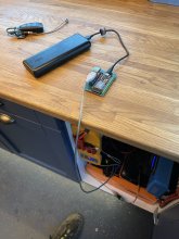
I'm using it to control the charge of Valence batteries in my Th!nk City -99 EV, so it's not with Solar panels in mind...
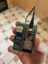
It's a much grittier project than t3chN0Mad's, with an USB-FTDI RS485 dongle and a separate Solid State Relay to end charge when first cell reach my specified voltage.

In the far horizon, I would probably build a complete EV BMS upon this foundation with contactor controls for charge and discharge, to also open contactors when voltage is low, but for now this suits my imminent need.

I leave no guarantees, and have not tested it more than briefly, but feel free to use and continue to build upon it.
I have not documented as pretty as t3chN0Mad's project either, but I think it's quite straight forward.

Included is a printscreen of the UI in action (Ran it on macOS over SSH to my Pi. The script does not work on macOS. It works in Windows if you remove GPIO-functions).
Do not run the software over SSH other than for testing, when the SSH session is terminated, the software is interrupted and stops reading, but the relay remains on.
View attachment 8423

Here's my repository (the folder RaspbPi contains my script);
Hey, thanks for your work on this. I have it running on a pi in my camper monitored via VNC Connect. Much better that having a Surface Pro with the Valance software.
 
Hey, thanks for your work on this. I have it running on a pi in my camper monitored via VNC Connect. Much better that having a Surface Pro with the Valance software.
I read the rest of the thread and wanted to acknowledge other contributions including t3chN0Mad for decoding the data.

And want to ask one question if anyone has noted - I know the internal BMS won't balance while "sleeping". But do the stats continue to update i.e. if I draw down x current/time is the internal BMS aware of that while external comms are not active? Maybe a different way of asking is will the internal BMS get out of sync with the battery under these conditions?
I know for sure that the SOC value does not update unless the battery is kept awake. The batteries are intended to be kept awake whenever they are being used. I also found that my Victron BMV700 does a FAR better job of keeping track of SOC than the internal BMS. The only thing I use the battery BMS for is to monitor if cell voltage or temperature is out of range and balancing the cells.
 
Here is a teaser for you all..... It does require one of the valence bms which is another long post. I've written a windows service that communicates to the valence bms through canbus. The service then uploads all of the data to an influxdb database for grafana and a mobile android app.inbound965690054951234207.jpginbound6159539015629641839.jpginbound1278068446147425862.jpginbound2012860192202022197.jpginbound2324821350970602558.jpginbound11564679653563049.jpg
 
Hi, I recently bought some p40-24, xp27-36 and higher voltage Valence batteries. Has anyone made an attempt to communicate with those?
Thanks.
 
The hardware looks very much the same, the software that was written for the 12V version will need to be altered to work for 8 cells. I see the battery is awake by the message but the data is not interpreted right. Anyone knows which changes to be made, my first attempt failed?

Thanks
 
The hardware looks very much the same, the software that was written for the 12V version will need to be altered to work for 8 cells. I see the battery is awake by the message but the data is not interpreted right. Anyone knows which changes to be made, my first attempt failed?

Thanks
So is it a 24 V battery or a 36 V battery. Or are you saying that you purchased 2 different types of batteries? I think their deserving of their own thread can you start one and post a link here?
 
Has anyone been about to get this BMS running on a Wemos D1 mini?. This area is completely new to me. Current having a D1 mini set up on a Breadboard with a Max845 and as far as I'm aware wired up Correctly and connected up with the batteries . Loaded the code onto the D1, set the pins but not luck yet getting it work and wake up the batteries.
 
Has anyone been about to get this BMS running on a Wemos D1 mini?. This area is completely new to me. Current having a D1 mini set up on a Breadboard with a Max845 and as far as I'm aware wired up Correctly and connected up with the batteries . Loaded the code onto the D1, set the pins but not luck yet getting it work and wake up the batteries.

Swapped a ESP8266 for a ESP32 as I saw User aguerrejoaquin has it working and used there code with a MQTT they posted a few posts back. i haven't yet figured out how to get there MPTT stuff to working. Going to try and get Blynk to run and seeing if I can output some of the information from the BMS to Blynk.

Seems to be mostly working. in Serial monitor I "Invalid readSOC"

using a MAX485 as well.

next job in the Final assembly and mounting

IMG_9261.JPGIMG_9262.JPGIMG_9265.JPG
 
Mounted to a perfboard now, wakes up the battery no issue but now have the problem of "invalid read" in the Serial monitor on seemingly all information coming from the batteries.
 

Attachments

  • IMG_9339.JPG
    IMG_9339.JPG
    102.1 KB · Views: 13
  • IMG_9340.JPG
    IMG_9340.JPG
    115.9 KB · Views: 12
  • IMG_9341.JPG
    IMG_9341.JPG
    139.8 KB · Views: 11
I am wondering if anyone has got the Arduino-XP-BMS code to work with a Mega board (I do see the ESPs above). I would like to use the Arduino Mega 2560 so I can merge this code with the code for getting a graphing interface on a LCD like in this project (https://www.nutsvolts.com/magazine/article/build-the-graphing-thermometer). I am running into compiling issues as it would appear the libraries for Teensy that are built in are not built into Arduino. I am especially having problems with the following sections of code:
Code:
    #ifdef hasAutoTxEnable
        RS485.transmitterEnable(enableRS485Tx);
    #else
        pinMode(enableRS485Tx, OUTPUT);
    #endif
    RS485.setTX(RS485Tx);
    RS485.setRX(RS485Rx);
I get compiling errors for this that transmitterEnable and setTX/setRX are not members of Hardware serial. I assume this is because Teensy has a built in library for this but Arduino does not. I found this library (https://github.com/sauttefk/RS485HwSerial) that appears to have many of the same functions but I am not sure what these Teensy members do and so what that would translate to in the RS485HwSerial library. Even if I do comment out the lines above that contain those I still get the following compiling errors:
HardwareSerial0.cpp.o (symbol from plugin): In function `Serial':
(.text+0x0): multiple definition of `__vector_25'
C:\arduino_build_656498\libraries\RS485HwSerial\RS485HwSerial0.cpp.o (symbol from plugin):(.text+0x0): first defined here
HardwareSerial0.cpp.o (symbol from plugin): In function `Serial':
(.text+0x0): multiple definition of `__vector_26'
C:\arduino_build_656498\libraries\RS485HwSerial\RS485HwSerial0.cpp.o (symbol from plugin):(.text+0x0): first defined here
HardwareSerial3.cpp.o (symbol from plugin): In function `Serial3':
(.text+0x0): multiple definition of `__vector_54'
C:\arduino_build_656498\libraries\RS485HwSerial\RS485HwSerial3.cpp.o (symbol from plugin):(.text+0x0): first defined here
HardwareSerial3.cpp.o (symbol from plugin): In function `Serial3':
(.text+0x0): multiple definition of `__vector_55'
C:\arduino_build_656498\libraries\RS485HwSerial\RS485HwSerial3.cpp.o (symbol from plugin):(.text+0x0): first defined here
collect2.exe: error: ld returned 1 exit status

Not a clue what these errors are. Any help would be much appreciated.

Maybe I am better going with a Teensy 3.6 and adapting the code from the graphing thermometer Mega to the Teensy? I have one laying around that I was using for another project and was able to get the code to compile for both using Teensy 3.6 so that is further than I got with the Mega.

Thanks.
 
Last edited:
I am wondering if anyone has got the Arduino-XP-BMS code to work with a non-teensy board. I would like to use the Arduino Mega 2560 so I can merge this code with the code for getting a graphing interface on a LCD like in this project (https://www.nutsvolts.com/magazine/article/build-the-graphing-thermometer). I am running into compiling issues as it would appear the libraries for Teensy that are built in are not built into Arduino. I am especially having problems with the following sections of code:
Code:
    #ifdef hasAutoTxEnable
        RS485.transmitterEnable(enableRS485Tx);
    #else
        pinMode(enableRS485Tx, OUTPUT);
    #endif
    RS485.setTX(RS485Tx);
    RS485.setRX(RS485Rx);
I get compiling errors for this that transmitterEnable and setTX/setRX are not members of Hardware serial. I assume this is because Teensy has a built in library for this but Arduino does not. I found this library (https://github.com/sauttefk/RS485HwSerial) that appears to have many of the same functions but I am not sure what these Teensy members do and so what that would translate to in the RS485HwSerial library. Even if I do comment out the lines above that contain those I still get the following compiling errors:
HardwareSerial0.cpp.o (symbol from plugin): In function `Serial':
(.text+0x0): multiple definition of `__vector_25'
C:\arduino_build_656498\libraries\RS485HwSerial\RS485HwSerial0.cpp.o (symbol from plugin):(.text+0x0): first defined here
HardwareSerial0.cpp.o (symbol from plugin): In function `Serial':
(.text+0x0): multiple definition of `__vector_26'
C:\arduino_build_656498\libraries\RS485HwSerial\RS485HwSerial0.cpp.o (symbol from plugin):(.text+0x0): first defined here
HardwareSerial3.cpp.o (symbol from plugin): In function `Serial3':
(.text+0x0): multiple definition of `__vector_54'
C:\arduino_build_656498\libraries\RS485HwSerial\RS485HwSerial3.cpp.o (symbol from plugin):(.text+0x0): first defined here
HardwareSerial3.cpp.o (symbol from plugin): In function `Serial3':
(.text+0x0): multiple definition of `__vector_55'
C:\arduino_build_656498\libraries\RS485HwSerial\RS485HwSerial3.cpp.o (symbol from plugin):(.text+0x0): first defined here
collect2.exe: error: ld returned 1 exit status

Not a clue what these errors are. Any help would be much appreciated. Thanks.
Mine in running on a ESP32 board, I couldn't get it running my Wemos D1 Mini / ESP8266. Arguably I did just copy the code a user posted here for there version with a mqtt but mainly has as they was also running it on a ESP32 based. unfortunately this area is just way above my knowledge and skillset to actually offer any support.

But in the version, I'm using the lines
RS485.setTX(RS485Tx);
RS485.setRX(RS485Rx);

have been commented out
 
I can post/sent you my code tomorrow. I'm using a mega2560 uC. I even did some testing with a 2004 I2C LCD.
Thanks Nick! That would be amazing! I am really challenging these batteries in our rv using them to run the ac and have a solar array (not to mention in Minnesota). So I would really like to be able to get some graphical feedback as to where the voltage, temperature and SOC are at.
 
Back
Top