diy solar

diy solar

Internal Resistance 280ah cells important questions

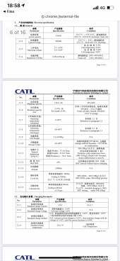
If it is really 0.36 milliohms near 25 degs C that is pretty poor for 280AH cell. If you have a current shunt in 0.1 to 0.5 milliohm range you can check your meter accuracy. (shunt mV divided by current rating = shunt resistance, 75mV/500 amp = 0.150 milliohms) Always check on battery terminals directly, not on top of bus bars. Low temp increases Rs (see attached pict) Full charge is a bit higher Rs. 50-80% SOC gives best Rs.

Most of degrading side chemical reactions that increase cell Rs also ties up lithium reducing capacity.

View attachment 56779
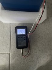
It was checked at 28C , it is hot summer now in EU, after 24 hours rest.

also device was calibrated and really carefully checked the contact code hen checked and did 5 checks for a cell to be sure , and lowest was considered .

So what I want is a graph with linear IR values …. For example if IR for new 280ah grade A is 0.18 mOhms than , 0.30mOhms is 50% lifetime = 80% of new capacity ? 0.40 mOhms is 20 % of lifetime remaining ?

What do you think from values of aged cells ?
Depends on what was the cause of degradation. Some things locks up more lithium then others. Capacity test will tell how much lithium is out of circulation. Loss of available lithium is directly related to loss of capacity. High impedance limits maximum current capability.

- hot temp and overcharge, damages electrolyte, clogs anode and cathode interface to ion transfer path. Higher terminal voltage drop vs current load, higher self discharge rate.
- high current, maintaining high state of charge, damages SEI (will regrow at cost of higher Rs and lithium consumption) and anode graphite cracks isolating sections of anode.
- many cycles, thickening of SEI layer, increases Rs and lower capacity due to lithium loss to grow SEI layer. Normal aging process.

Other issue you may have is keeping cells in SOC balance so BMS doesn't shut down everytime you go near full charge or get in lower % state of charge. Higher balancing current active balancer will help for this situation.

thank you for the answer .
it seems that if the factory has IR in 0.35
0.40 mOhms range it is a factory that uses bad production process and not using good quality raw materials.

B91AC1CE-DF9F-46FC-8BB3-000F69B6F194.png

9ECFD4DB-70D3-477B-8C4B-2512F7F344C6.jpeg
 
Depends on what was the cause of degradation. Some things locks up more lithium then others. Capacity test will tell how much lithium is out of circulation. Loss of available lithium is directly related to loss of capacity. High impedance limits maximum current capability.

- hot temp and overcharge, damages electrolyte, clogs anode and cathode interface to ion transfer path. Higher terminal voltage drop vs current load, higher self discharge rate.
- high current, maintaining high state of charge, damages SEI (will regrow at cost of higher Rs and lithium consumption) and anode graphite cracks isolating sections of anode.
- many cycles, thickening of SEI layer, increases Rs and lower capacity due to lithium loss to grow SEI layer. Normal aging process.

Other issue you may have is keeping cells in SOC balance so BMS doesn't shut down everytime you go near full charge or get in lower % state of charge. Higher balancing current active balancer will help for this situation.

Also when unpacking I was hearing electrolyte pouring inside each cell, this means that if I hear it there is gas + liquid inside the cells. Is this normal ?

Another thing is that all cells was transported horizontally, with terminals on the side of the box and not in the top, at night temperature and without UN3481 label or anything on the box, for 115 days in this position and temperature. Can a cell be affected if it stays with terminals on the side for 115 days ?

thank you
 
If it is really 0.36 milliohms near 25 degs C that is pretty poor for 280AH cell. If you have a current shunt in 0.1 to 0.5 milliohm range you can check your meter accuracy. (shunt mV divided by current rating = shunt resistance, 75mV/500 amp = 0.150 milliohms) Always check on battery terminals directly, not on top of bus bars. Low temp increases Rs (see attached pict) Full charge is a bit higher Rs. 50-80% SOC gives best Rs.

Most of degrading side chemical reactions that increase cell Rs also ties up lithium reducing capacity.

View attachment 56779

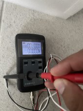
i calibrated the device and checked the accuracy before testing :

34289885-4717-45C2-95D8-EB0CB18439D8.jpeg
 
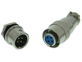
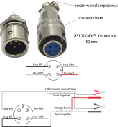
I found the 10 mm connectors at Marlin P Jones, Inc - MPJA.com.

Make sure you get the 10mm and not the 8mm size.

The white wires are the current drive, the red and black are voltage sense lines.

I made a extra test lead with larger strong alligator clips on current force white wires and DVM probes on red/black. Can clip alligator clips on bus bars and use probe red/black directly to battery terminals. Gives solid unwavering reading.

You will eventually break the twin pogo pin probes supplied with unit. Coaxial gold probes are probably better.

Voltage sense is very small signal so twist wires together to avoid interference pickup. Force 1Khz curent drive is fairly low, only about 0.5 mA rms so measuring 0.15 milliohm with 0.5 mA rms drive only produces 75 nanovolts. The meter has a narrow 1 kHz filter to improve the very weak sense voltage reading capability.

4 pin connector 10mm .png
 
First disclamer, I don't have verification on following statement regarding use of pre-lithiated graphite anode in recent cell fabrication.

There has been published success on pre-lithiating the graphite anode. The object of this is to add some lithium metal powder to graphite electrode to provide the initial lithium consumed during traditional cell charge forming and avoid some of the consumed 5% of the lithium from the cathode, which reduces cell AH capacity by about the same amount. The lithium is used in the SEI protective layer formation. Doing this has the promise of up to a 5% increase in cell capacity. It may partly explain the appearance of 300 AH cells. LiFePO4 and graphite particle size and conductive binders may also be part of the AH increase. 420 AH cell in a 280 AH size/weight cell is out of bounds of reality at this time.

Pre-lithiating anode also has the benefit to the manufacturer of reducing support charge forming stations reducing processing costs.

This process is new and some negative side effects may crop up. One possible side effect is a little more initial electrolyte breakdown that can cause some minor amount of cell bloating. Any electrolyte breakdown also creates compounds that coats electrode surfaces interface to electrolyte, blocking off some of the ion migration paths. This could explain some increase in cell impedance.

This would show up as greater terminal voltage drop at higher cell current (>0.5 CA rates).
 
Should I parallel these cells. 280ah. 16 bought 2021 Feb, 16 more just now.
2021 were said to be Eve, 2022 are docan power, claims to be made by Eve. Same physical sizes.
Different terminal distances. Different IR spec. 2021 say 0.15 and just now say 0.18 milliohm
Planning on one on one parallel up to 54 volts with one BMS unit.
What problems or issues am I in for ?
 
On above concerns. Should I make myself top of the new cells before paralleling them ? The year old cells are topped off right now.
 
Back
Top