diy solar

diy solar

Inverter and Charge Controller Shutdown Issue

Ed Tech Sensei

New Member
Joined
Apr 3, 2021
Messages
49
Here is my setup. BougeRV 12v, 180 watt solar panel, Giandel 1200w/2400w PSW inverter, Renogy Rover 40 amp MPPT solar charge controller, Battery Evo 120Ah battery X 2 in parallel. Renogy SCC will take 8 awg or smaller. 8 awg from Renogy to Giandel inverter. Anderson SB175, 6 awg from battery to Anderson SB50. SB50 8 awg cable to Renogy SCC. Connections are solid and tight.

Charged the batteries to 14.4 volts with 110 watts from the solar panel. No problem. Placed a 220 watt load on the inverter, monitored with a Kill-a-Watt meter. No problem. Placed a 470 watt load on the inverter with a heat gun. Inverter shut down after 5 seconds with a low battery warning. Both the Renogy and the Battery Evo display showed 13.7 volts.

Disconnected the solar panel from the Renogy. Disconnected the batteries from the Renogy. Connected batteries directly to the inverter. Placed the 220 watt load on the inverter (lights and a fan). No problem. Placed a 470 watt load on the inverter (heat gun.) No problem. Bumped the heat gun to HIGH pulling 1099 watts. No problem.

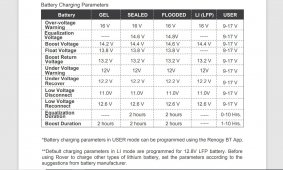
I think the discharge cutoff voltage for the Renogy is set too high. The spec sheet shows discharge cutoff voltage is greater than or equal to 10V but that doesn't make sense. Shouldn't it be less than or equal to?

Renogy discharge cutoff voltage.JPG
 
I am a little confused, you show the RNG-LFP (Renogy batteries) user manual, but you say you have Battery Evo 120Ah battery (https://batteryevo.com/) is that right?
I cannot see how Renolgy SCC will do anything to shutdown Giandel 1200w/2400w PSW inverter.
 
I am a little confused, you show the RNG-LFP (Renogy batteries) user manual, but you say you have Battery Evo 120Ah battery (https://batteryevo.com/) is that right?
I cannot see how Renolgy SCC will do anything to shutdown Giandel 1200w/2400w PSW inverter.
Sorry. I posted and referred to the wrong pic. The Renogy SCC low voltage disconnect is 11V. The battery never dropped below 13V but the Giandel gave me a low battery error light. I'll give it another go in the morning and record some video.
 

Attachments

  • Renogy undervoltage cutoff.JPG
    Renogy undervoltage cutoff.JPG
    176.2 KB · Views: 6
What is the exact model of your Renogy?
That under Voltage cutoff looks to be for the 12V Aux output, need to see user manual.
Renogy SCC cannot tell the Giandel 1200w/2400w PSW inverter to shutdown due to low Voltage unless you have the two units interface with each other some how to allow the Giandel to be controlled by the Renogy SCC, needs more details.
 
"8 awg from Renogy to Giandel inverter. Anderson SB175, 6 awg from battery to Anderson SB50. SB50 8 awg cable to Renogy SCC."

Are you feeding the inverter with #8 from the load connection of the controller by chance?
At any rate a 1200w inverter should be connected to the battery with #2 minimum if it's a short run......
 
What is the exact model of your Renogy?
That under Voltage cutoff looks to be for the 12V Aux output, need to see user manual.
Renogy SCC cannot tell the Giandel 1200w/2400w PSW inverter to shutdown due to low Voltage unless you have the two units interface with each other some how to allow the Giandel to be controlled by the Renogy SCC, needs more details.
Renogy Rover 40 amp MPPT Solar Charge Controller. The Giandel is connected to LOAD of the SCC with 8 AWG welding cable.

https://www.renogy.com/content/RNG-CTRL-RVR40/RVR203040-Manual.pdf

https://www.amazon.com/Renogy-Charge-Controller-Compatible-batteries/dp/B01MSYGZGI/ref=sr_1_3?crid=2S92847SZKO8R&dchild=1&keywords=renogy+rover+40+amp+mppt+charge+controller&qid=1619410311&sprefix=renogy+rover+40+amp,aps,233&sr=8-3
 
Last edited:
"8 awg from Renogy to Giandel inverter. Anderson SB175, 6 awg from battery to Anderson SB50. SB50 8 awg cable to Renogy SCC."

Are you feeding the inverter with #8 from the load connection of the controller by chance?
At any rate a 1200w inverter should be connected to the battery with #2 minimum if it's a short run......
I am feeding the inverter with #8 from the load connection of the controller.

Perhaps I don't understand how to set up my system. I connected my battery to the Renogy solar charge controller. Spec sheet for the Renogy states Max Terminal Size 8 AWG. Battery Evo sent a 6 AWG cable with the Anderson SB175 connector. 6 won't fit into the Renogy. Using an Anderson SB175 connector and 8 AWG, I made a short battery cable with a hydraulic crimper.

180 watt solar panel charged the battery to 14.4V. Running the inverter through the SCC, a 470W load for 5 seconds results in a low battery warning light on the inverter and shut down. SCC readouts look normal. I'm under the impression running a load to the inverter through the SCC is standard operating procedure. If not, why have load terminals on the SCC? Without using the SCC and connecting the battery directly to the inverter works great. Just seems like an extra step.
 
If you look at the user manual, the Load terminals are for Low current draw 12VDC load, not for inverter. You need to connect the Inverter to the battery output terminals, preferably with a circuit breaker or fuse that will handle the load current that the inverter will draw, I now see why your setup does not work properly.
User manual, please read the user manual
Page 10:
Warning: Do NOT connect any inverters or battery chargers into the LOAD TERMINAL of
the charge controller.

Page 27:
Rated Load Current Max is 20A.

 
Last edited:
The Renogy solar controller can handle a maximum of 20a at 12volts. Your inverter can draw150amps easily.

going to stop typing, Bud said it.....
 
If you look at the user manual, the Load terminals are for Low current draw 12VDC load, not for inverter. You need to connect the Inverter to the battery output terminals, preferably with a circuit breaker or fuse that will handle the load current that the inverter will draw, I now see why your setup does not work properly.
OK. So skip the load terminals of the SCC. Go directly from battery to inverter. I will have to build another cable with an inline fuse. Thanks.
 
Renogy should have put a warning sticker on that Load terminals, the surge current draw by the filter capacitors in the inverter can damage the output circuit of that Load terminals.
They should have also provide the wiring diagram for typical setup of PV panel, inverter, Batteries.

Pay attention to this also: Page 01
Charge Controller Safety
Important Safety Instructions
Please save these instructions.
This manual contains important safety, installation, and operating instructions for the charge
controller. The following symbols are used throughout the manual to indicate potentially
dangerous conditions or important safety information.
There are no serviceable parts for this controller. Do NOT disassemble or attempt to repair
the controller.
Make sure all connections going into and from the controller are tight.
NEVER connect the solar panel array to the controller without a battery. Battery must be
connected first.
Ensure input voltage does not exceed 100 VDC to prevent permanent damage. Use the
Open Circuit Voltage (Voc) to make sure the voltage does not exceed this value when
connecting panels together
.
I have short cables with MC4 connectors for the PV inputs. I always disconnect them first before the battery.

Open Circuit Voltage on my panel is 21.6v. I'm only using one panel right now.
 
If you look at the user manual, the Load terminals are for Low current draw 12VDC load, not for inverter. You need to connect the Inverter to the battery output terminals, preferably with a circuit breaker or fuse that will handle the load current that the inverter will draw, I now see why your setup does not work properly.
User manual, please read the user manual
Page 10:
Warning: Do NOT connect any inverters or battery chargers into the LOAD TERMINAL of
the charge controller.

Page 27:
Rated Load Current Max is 20A.

Battery Evo uses SB175 Anderson connectors. I would like to know if I can charge from solar and power the inverter at the same time. I can do this with a Jackery 500 because it has pass-through charging. Not sure how to connect the battery to the solar charge controller and the inverter at the same time.
 
This is the typical setup for PV panel to PV input of the SCC, then the Battery output terminals of the SCC to the Battery terminals, the inverter is then connected to the battery terminals.
Did you contact Renogy or look at Renogy website?
 
This is the typical setup for PV panel to PV input of the SCC, then the Battery output terminals of the SCC to the Battery terminals, the inverter is then connected to the battery terminals.
Did you contact Renogy or look at Renogy website?
I've seen that configuration before but my battery has a SB175 connector, not posts. I was thinking of making a very short Y-connector with one branch of the Y coming from the solar charge controller and the other branch of the Y with an inline fuse going to the inverter.
 
Well you just have to make some kind of adapter cables to allow you to properly interface all the component together.
I thought EVO come with cable with Anderson on one end to plug into the EVO battery pack and another ends have bare ends which you can install ring lugs and attach that to the busbars which become junction points.
 
Last edited:
Well you just have to make some kind of adapter cables to allow you to properly interface all the component together.
I thought EVO come with cable with Anderson on one end to plug into the EVO battery pack and another ends have bare ends which you can install ring lugs and attach that to the busbars which become junction points.
The EVO comes with an SB175 to a ring connector cable. I built an SB175 Y-connector splitting off to two SB50 connectors. One SB50 connects to the solar charge controller and the other to a fused line going to the inverter. I recycled some cables I already had. Works perfectly now.

Thanks for all your input!
 
SB50 is only rated at 50A, you have 1200W inverter which will draw about 115DCA for 1200W AC output. Also what wire gauge are you using?
 
Evo comes with 6 AWG wire and SB175 connector. I'm running 8 AWG wire. I have a 50 amp inline fuse in the line going to the inverter. I was able to pull 980W from a small space heater for 5 minutes without any problems. Wires to the inverter were warm to the touch but not hot. I reduced the load to 100W and the system maintained the batteries at 14.4v for 30 minutes. Input from solar was 255W from two BougeRV 180W panels in parallel.
 
Evo comes with 6 AWG wire and SB175 connector. I'm running 8 AWG wire. I have a 50 amp inline fuse in the line going to the inverter. I was able to pull 980W from a small space heater for 5 minutes without any problems. Wires to the inverter were warm to the touch but not hot. I reduced the load to 100W and the system maintained the batteries at 14.4v for 30 minutes. Input from solar was 255W from two BougeRV 180W panels in parallel.
980W at the AC output of inverter, that means the inverter will draw about 90DCA, that 50A fuse should have blown and you are using only 8AWG wire, and you also use 50A rated SB50. Something is not right.
 
Last edited:
Back
Top