diy solar

diy solar

Inverter and Transfer Switch Question

JoeTalks...

New Member
Joined
May 17, 2022
Messages
2
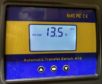
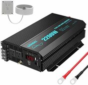
I am building a small battery backup system for my house using the system described on Will Prowse's page "2000 watt 24v Off-grid solar power system". My plan is to have this system so I can power some small freezers, etc. during a power outage. During times when we have power, I would like to use the system to power a few circuits in my house. Mainly lights, some small appliances, etc. My thoughts are to integrate the MOES automatic transfer switch by replacing two 20 amp breakers from my main power cabinet that currently feed the lighting circuits with one 40 amp breaker, then run the new 40 amp breaker output to the MOES switch as the grid supply. I am then going to run the output from the MOES switch into a small breaker panel and split it out into two 20 amp circuits to connect my original light circuits to. My question is how to integrate the inverter to the MOES switch. I ordered the Giandel 24v 2000 watt inverter, but now I am thinking I should have found an inverter with lug outputs instead of just the regular three pronged outlets. Is it possible to combine the two pronged outlets together via a buss bar so I can get them into one input to the MOES switch? I know they would have to be the same phase, but I can not find any documentation to show that they are in phase with each other.

Love the YouTube videos!

Joe

 
Even if they are on the same phase, I do not recommend doing this in the breaker panel. You should not feed 2 separate 20 amp runs from a common 40 amp breaker. An overload on one of the lines could result in the wire burning and could burn the house down. Each wire needs to be independently protected at a safe current level for that wire. You could feed both circuits from a single 20 amp, (more than a 2,000 watt inverter can provide) or you will need to branch it back out and still use two separate 20 amp breakers, not a single 40. You won;t get 40 amps for a 2,000 watt inverter, but if you go to grid mode, you need to be sure the wires are safely protected.

You should probably look into using something like a portable generator transfer switch. Something like this kit


With this one, you can select up to 6 circuits to get power from your inverter or the breaker panel. This one is meant for a 120/240 split phase, but it can also be wired for a single 120 volt output. If you search around, they also make smaller ones for 120 only.

If your inverter only has 3 prong outlets on it, you can use a cord, just like you would from a generator, but you must ensure you don't exceed the outlet rating. Are they 15 or 20 amp sockets? You would need to run 2 cords to feed 30 or 40 amps into the transfer switch box. That can be dangerous if it is wired for single 120 volt operation. 2 separate plugs need to go to separate busses in the transfer panel. Wire one to L1 and the other to L2. That way it is safe to plug into same or different legs without a chance of a short.

Is that 2,000 watt inverter just 120 volt out, or is it 120/240 split phase? 2,000 watts is really just a tick more than 15 amps at 120 volt. It's not really enough to feed two 20 amp circuits. It should run a refrigerator, a laptop, a phone charger, and maybe a few lights too.
 
I had planned on adding two additional 20 amp breakers in the second panel to keep the circuits protected independently. The manual doesn't say what the sockets are rated for. I would say 15 amps to be on the safe side. I believe it is only 120v. I bought it on Amazon, and they were not advertising it to be split phase. I am trying to capture two circuits only because I put them in and I know the loads are significantly under capacity for the wiring and breaker I used. Plus I am familiar with how and when the circuits get loaded. I would normally only try to capture one circuit if I knew it was at full capacity. It sounds like maybe this isn't such a good idea if I don't have all the data on the inverter. My thoughts were that if I pulled too much through the inverter, that it would give me an overload fault, then could reduce the load if needed. Just trying to supplement as much from the grid as possible. Thanks for the help.
 
I had planned on adding two additional 20 amp breakers in the second panel to keep the circuits protected independently. The manual doesn't say what the sockets are rated for. I would say 15 amps to be on the safe side. I believe it is only 120v. I bought it on Amazon, and they were not advertising it to be split phase. I am trying to capture two circuits only because I put them in and I know the loads are significantly under capacity for the wiring and breaker I used. Plus I am familiar with how and when the circuits get loaded. I would normally only try to capture one circuit if I knew it was at full capacity. It sounds like maybe this isn't such a good idea if I don't have all the data on the inverter. My thoughts were that if I pulled too much through the inverter, that it would give me an overload fault, then could reduce the load if needed. Just trying to supplement as much from the grid as possible. Thanks for the help.
I still think that using a portable generator type transfer switch is a good option. You can then switch those two circuits to either get power from the main panel, or from the generator outlet. The generator outlet can get it's power from any inverter or generator that can provide enough power. You can run the output from the Giandel inverter into the generator input.

If the inverter also has a mains input to charge from the grid, you could also have a plug off the main panel to power that. Some inverter/charger units like that even have an automatic transfer switch built in. I am not familiar with the MOES transfer switch you were looking at, but I have seen a few, and it can probably be made to work, but you will need to add the extra breakers on the output to properly protect the 2 circuits.
I have used this Portable Generator Switch for several years ( https://tinyurl.com/khkerees ), with a generator and now with solar. I can simply plug the generator or the solar into the inlet box on the side of the house. It is hard wired in and has breakers. All the switches are BBM (Break Before Make) switches so there isn't the chance of sending your generator or solar power back up the grid, endangering electrical workmen attempting to restore a down grid.

My primary is the solar but here in Oregon, grid is the primary. My solar is NOT GRID-TIED.

The grid goes down here quite frequently so we need backup.
 
I have both, the 2200 Giandel inverter and the Mose ATS.
I have it wired so that the grid feed is live when the ATS is manually turned - Off
When the ATS is Manually turned On, the Grid feed is disconnected and the circuit is opened to the Giandel
NOTE: The Mose ATS does not activate the Giandel to On
If the Giandel is manually turned On, the inverter draws from the battery bank to supply 110v
When the battery bank is drawn down to 11.5v DC, the Mose ATS will drop off and the Giandel will power Off
Grid 110v power is restored

My issue is: If the Giandel is On and the Mose ATS is Manually powered Off, / Grid On + Giandel On
(not following the correct Power Off sequence or the Mose ATS re-activates)
I will have the Giandel supplying 110v to my breakers at the same time the grid is On
The Mose Power switch is a manual On/Off switch,
I can automate this by attaching this feed to a continuous duty relay
(add or remove power to the relay coil)
The Giandel Power switch has a flip/flop activated switch (Press On-Press Off)
I'd like to automate this Power On-Power Off sequence but I'm not sure how to activate-deactivate the Giandel
Any suggestions?
 

Attachments

  • 2023-12-21 (1).jpg
    2023-12-21 (1).jpg
    155.4 KB · Views: 0
  • Giandel 2200 Inverter.jpg
    Giandel 2200 Inverter.jpg
    36 KB · Views: 0
Last edited:
The ATS controller will switch to grid power when batteries voltages are lower than cut off point,
it will switch back to battery power when the batteries voltage are higher than recovery point.
Not good if the Giandel is powered on
Grid is = On
Inverter is = On
Charger will be Off
~~
Grid is On
Inverter is On
Solar is On
Charger will be Off
~~
Grid is On
Inverter is Off
Solar is On
Charger will be Off
~~
Grid is On
Inverter is Off
Solar is Off
Charger will be On
---------------------
I can accomplish this by adding Continuous Duty relays to control the voltage for each device
]Grid is OFF, the ATS is On, inverter should be On, Interrupt the 110v circuit to the battery charger /OFF
]Grid is ON, the ATS is Off, inverter should be Off, Activate the 110v circuit to the battery charger
Basically, by taking a signal voltage from the ATS, you can power this relay from an OFF state to a ON state
If the ATS is On the relay coil is On, (NO), the inverter should be On and the 110v circuit is broken
(I didn't discuss the fuses because those should be obvious)
The point of this is to keep the Inverter from running while the 110v backup generator is ON
 
Last edited:
Inverter output to residential grid question: my small 48-volt solar panel and battery bank will supply power needed to run one hybrid DC>AC inverter delivering maximum 120 volt 41.67 amps for use in my home electrical system; wired to a bus bar from which two (2) 120-volt 20-amp circuits will be connected into my existing utility powered 100-amp service panel. Distribution cable for each circuit will be sized at 80% of wire ampacity (per NEC) or three-wire 10awg copper sized to meet 80% ampacity rule or 26.04 amps (10awg is rated 35 amps) fused at 30-amp cut-off. Consequently, more than 20 amps might find their way down one of these lines, but with the 30-amp fuses (CB) in place, neither circuit will be capable of accepting more than the wires can safely handle.

Priority schemes and transfer switching are all handled internally by the hybrid inverter, so whatever the power source at the time (solar, battery or utility) the product of this inverter will come out of this 40-amp output port and will be capped at that upper limit.

Summary: Inverter 120-volt 40-amp Maximum Output to Bus Bar, split into two (2) 20-amp fused circuits feeding into my home residential panel; sharing to whatever extent the loads of the other circuits supplemented by the utility grid.

That's how I am seeing it. I don't want to build it and then find out my plan was flawed. Do you agree with this approach? Or have I missed the point?
 
Last edited:
Back
Top