diy solar

diy solar

Inverter Bypass - in a 2 1/2 inch or 3 inch conduit

jasonhc73

Cat herder, and dog toy tosser.
Joined
Oct 1, 2019
Messages
1,921
Location
Wichita, Kansas
I am about to relocate my setup from my garage to my utility room.

Right now I back feed my panel through a 6awg 50 amp circuit breaker.
I have been doing this for over a year. Now I have gained enough confidence in the reliability of MPP-Solar stuff that I am 90% convinced myself to switch my topography so that everything just goes through the inverters and directly to the mains on the panel.

As it is now from my main net-meter to the service panel I have 3 x 4/0 AL. I plan to hijack it and put a safety disconnect and my off-grid inverters and battery in the middle.

The service entrance is through a 2 1/2 inch schedule 80 PVC conduit. At the base to under the house a big elbow entering the crawl space. My plan is to send that cable to and from my utility room, 12 feet in total.

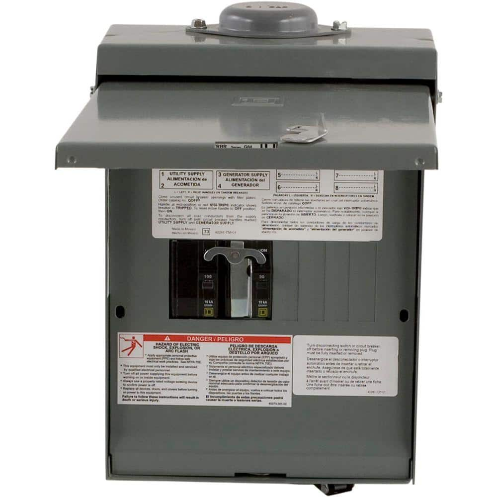
Can I just put a single hole in the box(look at the picture) I have and put my cables in and butt splice the one cable to the panel cable?
20210208_173300.jpg20210208_173308.jpg

I think I will feed the wire into the meter directly. I see no sense in having two sets of butt splices.
IMG_20191015_153738629.jpg

I am not sure two sets of 4/0 will fit in a 2 1/2 conduit. I am sure it will fit fine in a 3 inch though.

Is there anything wrong with having two sets of A/C in the same conduit? One going and One coming to/from the inverters and safety disconnect?
(the little squiggly that looks like a N or 2 is the A/C symbol)
New-1.jpg

These inverters, MPP-Solar LV6548's, have a configuration schedule that can program them to not use any grid power and only charge from the sun during a set time. This is great for me. My state has a totally weird demand tariff in place for solar users. So if I can force my house to only use my batteries during this time, I will completely avoid the tariff. Just in case I am not reading the instruction right, I can turn the grid off with the safety switch and force the inverters into off-grid mode physically.
 
It is fine to have multiple wires in conduit, including coming/going.
More than 3 current-carrying conductors in a conduit requires derating, so calculate according to table of NEC chart.

There are conduit fill charts, but just because the wires could fit in a conduit, doesn't mean you'll be able to pull them.
All my conduits, 3/4", 1" , 1 1/4", 2", are getting stuffed to the point I may not get another I want through them. Put in oversize conduit.

Things fail, so I suggest having switches you can through to bypass the inverters, keeping house running from grid and turning off power to all wires of inverter so it can be disconnected. I have several disconnects and interlocked breakers for that purpose.
I was thinking about using a generator transfer switch. But that simply started to get unnecessarily complicated.

The fill chart I found showed 6 4/0 will fit a 2 1/2. the inside of the one I have now is 2 1/2, and It looks like it is filling more than half the conduit, but it is double insulated also.

Can you show an example of what a bypass would look like? A 200 AMP bypass.
(Last page of this from OutBack looks about right https://www.outbackpower.com/downloads/documents/appnotes/ac_input_output_bypass.pdf)
 
Last edited:
Can you show an example of what a bypass would look like? A 200 AMP bypass.

You just added "200 amp" ...

My house is remote from garage with service entrance. I used this box to select grid (wire from main panel) or inverter as the source powering house. It came with 100A and 30A breakers. I changed those to 70A and 70A (have 6 awg to house). Normally always fed from my Sunny Island as UPS, but just throw the switch to go back to grid.


The main panel has 200A main. I installed a 100A backfeed breaker, so I can power the garage from the inverter as well. For now, inverter also gets grid from this same panel, so manually shut that off to keep inverter output from feeding inverter input. Backfeed breaker is interlocked with the following:


Service entrance and meter is actually a separate box, with its own 200A breaker. So I plan to tap off input to Sunny Island between service entrance and main panel. That will give me more flexibility, including powering garage from UPS rather than having to manually switch it from grid to inverter.

200A transfer switches are hard to come by. Not sure how your meter vs. panel are configured, but maybe 200A breaker coming from grid and 100A or 125A backeed coming from inverter would work, if you can insert a "Y" connection so grid & meter feeds both your inverter input and the 200A main in a panel. Or do you have 200A of inverter output?
 
After studying the outback schematic, It is much simpler than I thought to make a bypass circuit.

Thanks!

Right now, I only have 100 amp of inverter output. But the service panel has 4/0 from the meter. It's way over kill for my use, the most I have ever drawn was 11.2 kW showing on the meter, that's about 95 amps I think. I don't know how I did it either, maybe charging my car at 32 amps and the Air conditioner and the dryer were all on, I dunno.
 
Turns out, this is exactly twice what I want/need for my two inverters to have a manual bypass and all necessary circuitbreakers.

4 - 50 amp breakers and 2 100 amp breakers.

Bypass.jpg2021-02-08.png
 
Right now, I only have 100 amp of inverter output. But the service panel has 4/0 from the meter. It's way over kill for my use, the most I have ever drawn was 11.2 kW showing on the meter, that's about 95 amps I think. I don't know how I did it either, maybe charging my car at 32 amps and the Air conditioner and the dryer were all on, I dunno.

Just seeing bottom half of meter, I'm not sure what I'm looking at.
Wires straight to meter socket, without disconnect. Aluminum wire, also smaller wires.
You have access.
Must be after the meter, grid is on opposite side.

If you had a 200A breaker at the meter, and another at the breaker panel, that would give flexibility wire wire various ways needing utility to shut off power.
 
Turns out, this is exactly twice what I want/need for my two inverters to have a manual bypass and all necessary circuitbreakers.

4 - 50 amp breakers and 2 100 amp breakers.

View attachment 36460View attachment 36461

100A bypass, 2, 50A in parallel for inverters.
All an Outback panel and breakers?

I had problems with multiple QO breakers in parallel, differed in resistance so current didn't split evenly.
Solved by using Schneider DIN mount miniature breakers. Outback probably work fine as well.
 
100A bypass, 2, 50A in parallel for inverters.
All an Outback panel and breakers?

I had problems with multiple QO breakers in parallel, differed in resistance so current didn't split evenly.
Solved by using Schneider DIN mount miniature breakers. Outback probably work fine as well.

I can make this with anything really, now just hunting down the parts. It is not that complicated after studying it for a few hours. ?
 

I can make this with anything really, now just hunting down the parts. It is not that complicated after studying it for a few hours. ?

The key to making it work is an interlock that makes it impossible to ever connect output of inverter to grid.

My Square-D interlock in main breaker panel is attached to the cover. Cover removed, it is possible to turn both on. There is a bracket securing the backfed breaker with a warning label. It only interlocks one 2-pole breaker.

Outback has rigged up a plate to interlock one 2-pole 100A with two, 2-pole 50A.

There are some other DIN rail parts out there, with multiple breakers or switches internally ganged. Some I would trust more than others.

And then there are some rotary switches, and some visible-blade switches.

Doesn't sound like you have a generator. For my SMA equipment, manual says to have 5 second "off" time when switching inverter between two different sources (to ensure it disconnects, doesn't try to backfeed out of phase.)
 
This is what I have finally found.

The "EVERYTHING" in a box. :) About $700 I think, maybe $550, still fuzzy on what it comes with as configured for I/O/B.

 
Our electrical panels cost as much as some people's inverters.
Low cost things can be assembled with breakers sourced direct from China (as opposed to those sold by big names, manufactured in China.)

Here's reference to one I found. It started buzzing so I didn't rust it, replaced with the Square D generator switch.


That was $20 for a 63A 2-pole transfer switch. Another model claimed 100A.
The European one I found could be assembled with many poles, so could do that 2x100A + 4x50A
 
I have a GS4048 and didn't buy the GS load center. You can run everything through separate circuit breakers if you want.

So you are trying to wire grid into the GS grid input and your panel into output of the GS. Word of caution when doing that. The GS can only flow so much power and you will not be able to use any inductive loads like heaters, elec ovens, and water heaters of any larger size. I have a friend that ended up buying multiple GS8048's to stop lights dimming when larger loads turned on. He is powering his whole house. I have a critical loads panel and run a smaller load through the inverter.

Not sure why you would want to tap into your meter. If you do tap into the meter you are best to have beakers at the meter and at the Outback inverter because current can flow both ways so really should be fused to protect in both directions. Remember breakers protect the wire and should be sized to the wire size or smaller(breaker can always be smaller).

If you keep the GS wired into the top breaker and you can find a "Generator interlock kit" (google) that works with your panel. This will be the bypass and the I/O/B the way I see it.

Not sure you need a transfer switch....The GS will take care of transferring the load if wired right. The GS is pretty much an auto transfer switch.

There are more options but I don't know your whole plan and don't want to make this more confusing then it needs to be... Good Luck.
 
Last edited:
I have a GS4048 and didn't buy the GS load center. You can run everything through separate circuit breakers if you want.

-snip-.

There are more options but I don't know your whole plan and don't want to make this more confusing then it needs to be... Good Luck.
This is a little more of the bigger picture of my setup.
IMG_20190905_110748497.jpg
The smaller red and black wires are from my grid-tied setup, a 6.2 kWp SolarEdge system, it back feeds the grid.
IMG_20191015_153738629.jpg

My state has a demand tariff from 2:00 PM to 7:00 PM where if I happen to use any grid power during those times I get to pay $3 per kW in the winter and $ 9 per kW in the summer.

So to mitigate this problem, I turn the mains off at the loads panel. The grid-tied system still operates and now feeds the grid when I turn my house off from the grid.
IMG_20190820_234908020.jpg

A solution then is to put an interlock on my panel. Right? Well, not exactly. The off-grid system that I use is not very big, it is 3.5 kWp. But now it is only getting about 1.5 kW of solar due to the winter sun being much lower. The only way I can have my off-grid power my entire house, and charge the batteries is from the same outlet. The solution that I have is a giant knife switch that changes the plug on my panel to the input or the output on my inverter.
IMG_20191228_204606452_HDR.jpgIMG_20191228_204944366.jpg

Being able to switch the "off-grid" setup to be grid-fed lets me recharge the batteries overnight when there isn't enough solar to charge them.
I don't have a "critical-loads" panel, I have a loads panel! "ALL LOADS MATTER!" ??

The new inverters that I just swapped out have a time of use schedule that makes it programmable to not use any grid power during the times I set. So, therefore I can just stop doing all this manual switching.

Now back to the Outback LCS box. After sleeping on it overnight, I put the crack pipe down of finding exactly what want and realized that $1200 is an insane price for 6 circuit breakers and some wiring in a metal box. That is literally all the LCS is. The LCS is not even what I want, which is 200 amp capable. Even the 175 amp DC side isn't what I want, I regularly use 165 amps to charge my car.
 
The Outback GS is very flexible…..almost to flexible which makes it very hard to understand the manual. A lot of the manual can be skipped....if you don't have a component then that section isn't used or the section on the Mate3 isn't used even though it is there and you can change the settings.

You can do grid zero during certain times, back feed with excess power, frequency shift to shutdown inverters during grid down if making to much solar.....

I thought the GS load center was way to expensive for what it is, though it is UL listed.

Have you bought the GS unit yet? There are many newer options. Here is a good list of many of them.

Guessing you first need to know your big loads and if they can go through the GS. And then start figuring out how to rewire.
 
My state has a demand tariff from 2:00 PM to 7:00 PM where if I happen to use any grid power during those times I get to pay $3 per kW in the winter and $ 9 per kW in the summer.
One of my installations in California has a demand tariff which is fairly common with commercial properties. Here it is a monthly rate based on the maximum demand during anytime. For a moment, I thought you left out the hrs part of the rate but now I understand. I forgot the rate but it amounts to $25 per month. I have solar on the building but let a tenant charge his car and I think he at the most he is using 2kW.
 
I have finally discovered the simplest solution for this bypass safety switch.

Instead of some elaborate $1200 box with 16 circuit breakers and way too much "engineering".

I finally realized that I only need 2 - 240-Volt Non-Fuse Metallic AC Disconnects to do this.

$1200 pre-made solution simplified down to about $30.

One disconnect is on the main power line. It will be labeled input and output.

I will put two sets of lines on both connects. One is from the grid and the other goes to the AC input of the inverters.

The other is the output, this will go to the out of the inverter and the loads panel.

Here is the magic of simplicity. The second AC disconnect is between the inverter output and the first ac disconnect.

When I want to bypass the inverters, I pull the disconnect plug from the second disconnect and insert it into the first disconnect.

None of this needs to be fused or have circuit breakers. Having only one plug means it is impossible to have output and input at the same time.
 
What are the load ratings of those disconnects? I am having a hard time imagining where the circuit breakers are for those connections? I understand the disconnect does not need to be protected. I was trying to understand the circuit you described. If it works for you then that may be all that matters. I would just use an interlock and two circuit breakers positioned to accomplish the same thing. An interlock also costs about $30. Had you considered an interlock and the simplicity of that solution?

I am also not sure that two conductors are allowed to be attached to the lugs of those disconnects. Is this a code compliant installation?
 
Last edited:
Back
Top