diy solar

diy solar

Inverter Bypass - in a 2 1/2 inch or 3 inch conduit

What are the load ratings of those disconnects? I am having a hard time imagining where the circuit breakers are for those connections? I understand the disconnect does not need to be protected. I was trying to understand the circuit you described. If it works for you then that may be all that matters. I would just use an interlock and two circuit breakers positioned to accomplish the same thing. An interlock also costs about $30. Had you considered an interlock and the simplicity of that solution?

I am also not sure that two conductors are allowed to be attached to the lugs of those disconnects. Is this a code compliant installation?
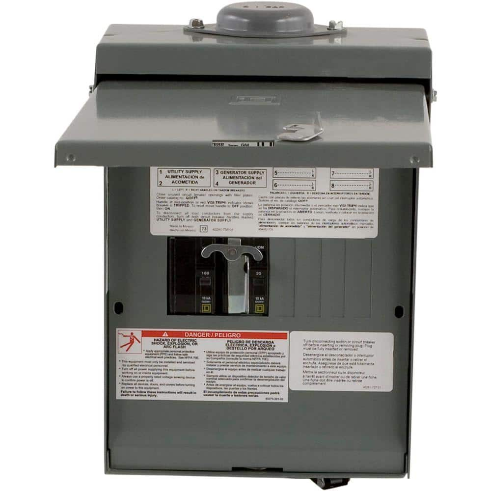
Pretty light "topographical" drawing here.
img002.jpg
It shows L1 and L2.
The N/G are sent through and not on the drawing for simplicity of the drawing.
PV inputs and DC Battery inputs are not shown for simplicity.

An AC disconnect is a "plug" that is used as a "double jumper". This double jumper connects the lines. As long as only 1 jumper is used (and the other is thrown away). This circuit can never back feed the output of the inverter.

So far, the largest rated AC disconnect I have found is rated for 60 amps, which is 14,400 watts.
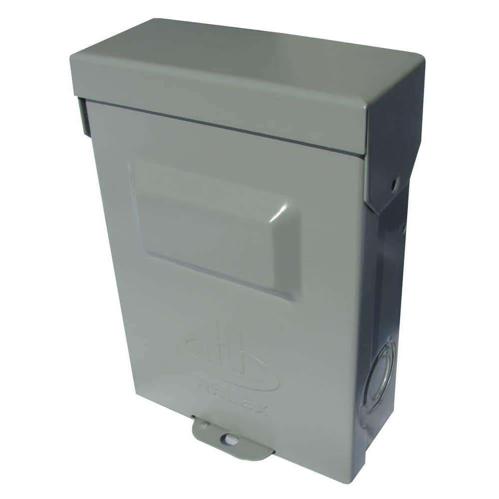
In my case, the largest load I have ever had on my service net-meter shows 11,318 watts. I normally never do more than 4,000 watts, but I can easily do 7,200w just charging my car at 32 amps, but normally I just do 10 amps.

The plan is to have the plug put in position 2 all the time. If in the future an inverter gets replaced, the plug gets moved to position 1 and bypasses the inverters.
 
Last edited:
However, there is nothing to prevent two plugs from being inserted, one in disconnect #1 and one in disconnect #2.
That is, nothing except that you have disposed of one plug. It can be replaced. Even if you think you have made if foolproof ...

$8.98 per disconnect. I can't come up with anything cheaper than that (unless they both get plugged in, in which case cost increases to at least the price of your inverter.)

Here's what I used:


It came with one 100A and one 30A breaker pre-installed. I replaced those with two 70A breakers.

(I pretty much stopped worrying about how much I spend some time ago. It is nothing but mouse clicks now, doesn't feel like it used to.)
Show your installed switch.
How is it wired?
 
Show your installed switch.
How is it wired?

The interlock is attached to breakers rather than removable bezel like other models, better because doesn't allow both breaker on at once.
Generator inlet plug disconnected; all wires tied to ground bar.

Panel busbars wired to house sub panel.
One breaker wired to a breaker in main panel.
One breaker wired to inverter output. Because the inverter output also wires to a backfed/interlocked breaker in main panel, wires spliced with split nuts (seen here.)
Inverter wires are 2 awg. The others are 6 awg.
I left lots of extra length ("service loop") to allow future rearrangement.

house interlock.jpg
 
I actually just realized that I missed the entire point of my bypass circuit.

I need one more AC disconnect for the input side of the inverters also.(my original thought was one of the big on-off throw switches This will certainly work. But now that I have figured out the topography of the AC disconnect AND bypass, it makes little sense to me to spend the money on the big handle switches. If there were a way to lock them out like how @Hedges shows but with all three that is what I want. (but not $1200 want)

The whole point is to disconnect the grid from my house. That way there is absolute certainty I am 100% solar/battery off-grid.


PS - Back to the original post and pictures

What kind of dope tries to stuff another cable in the same conduit, when he can just add another conduit?
I mean really, duhhhhh.
I just realized this after drawing the topography lines.
This is something that Occam will appreciate. Just add another conduit right next to the other one and feed the new line in and out of it to the old line that is there. "KISS principle"
IMG_20191015_153738629.jpg.

Ver 3 drawing.

img003.jpg
 
Last edited:
Any fuses or breakers between the grid and input of your inverter?

That image of meter - are the wires we see coming from utility or going to your loads?
It's not the 3 wires plus ground I'm used to on customer side, and there isn't a wire to ground rod. Even the smaller gauge wires going off to right don't have a separate ground.
 
Back
Top