diy solar

diy solar

Inverter Bypass Switch Help

GunTotnHippie

New Member
Joined
Jan 7, 2020
Messages
17
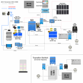
I recently had a Victron Quattro 24v 8000 230v inverter die on me. I have contacted the vendor and now have to send the unit back. The inverter went into overload condition and I believe the PCB is now blown. The system is in a RV with 50amp connection. We decided to install an inverter bypass using a midnite solar transfer switch. The only thing I can figure is that when the switch is switched to bypass the 120v is back-feeding back into the Auto Transformer which was then back-feeding to the inverter. I could have also received a bad unit but the problem didn't start to happen until I was swapping out a battery in the bay and I think the DC wire may have moved the transfer switch to bypass. I am now trying to create a new bypass switch as the tolerance of the midnite solar switch is not very good and therefor allowing the breakers to be on or off at the same time (Bad design). The attached diagram shows the circuit in the bottom right hand corner. Does anyone know of a way to do a bypass with a rotary/cam switch or another option? The idea here is to have a single switch so it doesn't confuse anyone trying to work on the system.
SolarSetup.png
 

Attachments

  • signal-2020-10-08-174829.jpeg
    signal-2020-10-08-174829.jpeg
    118.7 KB · Views: 15
Want to add that I have asked both the vendor and a repair center if the back-feeding issue can occur. Both have stated doubtful but I can't get a straight answer on this. I don't see it in Victron's documentation.
 
Are those two 2-pole DIN switches (or breakers) interlocked so they serve as a transfer switch but can never both be on at he same time?

I've seen some that are interlocked
Rotary switches with 2P2T can do it.
My home breaker panels are Square-D QO and I use interlocked main/backfeed breaker in them. A number of brands offer that.
They are interlocked through the front panel but the metal is flexible and the tolerance of the holes that the breakers go through is not the greatest. Can you explain in more detail on how to pull off a rotary switch to do this? I am figuring I need a 4 pole cam switch because I need to isolate the circuits between the Transformer and AC loads and AC loads and the 50amp input. I need to figure out what size cam and how to wire it. I am figuring I will need a 125amp or more rating.
 
Also wanted to note that I am using #10 THHN wire so I will need enough room to support all of those heavy wires.
 
Here's a switch that says "on-off-on" but then says 3pst which contradicts that:


I've seen some up to 200A but not frequently. Some are 4PDT. This one says 3-phase but appears to be DPDT:


Here's a brand of DIN switch I came across. They also have 63A, and pieces that can be stacked for higher amperage. Overseas vendor, though:


Another brand, 125A


I got some 63A interlocked breakers out of China, but don't trust them after hearing a buzzing. So I'm replacing with a Square-D panel.

This has a 30A breaker for generator but I think busbar is 100A and other breaker is 100A, could replace the 30A

 
Do you have a diagram that demonstrates how the cam switch would be wired up? I have thought about this but I don't know why my brain can't figure out how to wire it up with all these wires. 1 - AC, 3 - AC Load, etc.. Mind you there are 2 legs wired to each component. Also does the neutral get wired into the cam or do I use a neutral block?
 
Neutral would go to a block.
Obviously each hot would go to either grid or to inverter, and the switch needs to be "off" in the middle, a.k.a. "break before make"
Each switch looks different physically. I don't even have a drawing of that one rotary switch, but I picked up a 4PDT switch myself.
Some switches (like the DIN ones)have completely separate DPST switches for grid and "generator", so one side has to be wired common and connected to load (your panel). Others have it as a DPDT switch, 6 terminals.
Always good to check continuity with an ohmmeter before connecting.
 
I have the Outback AC panel which is same design and is really bad. I basically make sure the one set of breakers is fully off before the others flip on. It basically just relies on a metal plate that slides over all the breakers in the set with half the breakers turned upside down. Here's a pic I found of it: breaker.
 
Back
Top