Rec-Bms has a precharge to automatically pre charge the circuit 11-68 volts with a 4 second delay (programmable 2 to 11 sec delay) for use with a contractor (main relay).
You are using an out of date browser. It may not display this or other websites correctly.
You should upgrade or use an alternative browser.
You should upgrade or use an alternative browser.
Inverter capacitor charging spark!
- Thread starter atatistcheff
- Start date
If I was using a contactor with my BMS I would use a toggle switch plus a push buttonI have the same 50-ohm resistor (as seen in mrnatural22 photo )connected in series with a push-button switch. These two are then connected across the terminals (in parallel) of my 100 amp circuit breaker that is in series with the positive lead of my battery.
Before I switch on my breaker, I hold the push button switch for about 5 seconds then let go of the button and switch the breaker on.
I don't ever see any sparks anymore and when testing the resistor current when pushing the button, there is very little and prevent that spark. - It works for me!
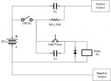
The toggle switch is used as a Master OFF/Precharge ON. Flip it off any time you want to disconnect the battery output. The toggle switch can be a low current switch (3A is plenty) since all it is doing is suppling the inverter cap precharge current and powering the contactor relay coil.
To turn power on:
- Flip the toggle switch to On
- Wait a second
- Press the High Power button
What does that cost?Rec-Bms has a precharge to automatically pre charge the circuit 11-68 volts with a 4 second delay (programmable 2 to 11 sec delay) for use with a contractor (main relay).

Not terrible, not cheap, but not terrible either.
One of these would provide the timer function.
FilterGuy
Solar Engineering Consultant - EG4 and Consumers
For those of you that have not seen it before, you might want to check out this resource:
https://diysolarforum.com/resources/inverter-disconnect-switch-with-precharge.60/
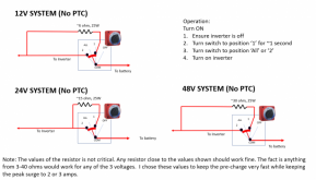
Note: I use the Perko battery select switch because you can not go from off to '2' without going through '1' first.
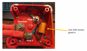
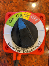
I create a custom lable for the switch
https://diysolarforum.com/resources/inverter-disconnect-switch-with-precharge.60/

Note: I use the Perko battery select switch because you can not go from off to '2' without going through '1' first.

I create a custom lable for the switch

FilterGuy
Solar Engineering Consultant - EG4 and Consumers
As you point out, there is not much detail in the description so it is hard to guess what is inside it. My guess is it is a pre-charge through a resister and a bank of FETs that don't turn on till the voltage at the inverter gets high enough.I like that the CSL500 doesn't require remembering to precharge/knowing if the capacitors have dissipated, but I'm curious what the other pros and cons are.
The two 'cons' I would worry about are
1) what is the effective resistance when it is 'on'? With the kind of current we put through large inverters, even a tiny resistance would create a lot of heat/energy loss. Judging by the size of the metal case, my guess is there is a significant energy dissipation across it. This also means there will be a voltage drop across it so your inverter will 'see' a lower voltage than what is actually at the battery.
2) What is the reliability of the product?? Anytime you add something to the system, the overall system reliability is impacted by the reliability of what you add. With high current devices such as this, careful design is necessary to have good reliability.
Note: I have never touched a CSL500 so I don't know if either of my concerns are real or if the paranoids are out to get me.
I just looked at that a bit more carefully. It requires a BMS that switches the battery positive rather than ground like the vast majority of FET based BMS so. It would work as is, with an Electrodacus BMS and obviously a Rec-BMS.Rec-Bms has a precharge to automatically pre charge the circuit 11-68 volts with a 4 second delay (programmable 2 to 11 sec delay) for use with a contractor (main relay).
You could use a FET based BMS with the Rec BMS Precharge if you added a relay so the BMS switches battery positive.
I was thinking about how you would combine my circuit with a FET based BMS and came to the realization that my system would also require the BMS to switch the battery positive so that the battery wouldn't supply current out the precharge resistor if the BMS disconnects the battery. I would just add a small solid state relay to my circuity to do this.
The guys at Rec-BMS already figured that out. It makes sense why Rec-BMS didn't do that for their solution. They are selling this as an accessory to their BMS which must switch battery positive. Makes the Rec-BMS less attractive to those wanting to use a cheap FET based BMS to drive a contactor.
Good points.1) what is the effective resistance when it is 'on'? With the kind of current we put through large inverters, even a tiny resistance would create a lot of heat/energy loss. Judging by the size of the metal case, my guess is there is a significant energy dissipation across it. This also means there will be a voltage drop across it so your inverter will 'see' a lower voltage than what is actually at the battery.
2) What is the reliability of the product?? Anytime you add something to the system, the overall system reliability is impacted by the reliability of what you add. With high current devices such as this, careful design is necessary to have good reliability.
It's suspicious to me that they don't list a Maximum Current...
I'm planning to use it since it's required for BattleBorn's warranty, but maybe someday I'll upgrade to a custom pack.
If it proves unreliable I'll do a teardown and then switch to the perko battery option you describe, that's really slick to just have the charge be a point along the way.
Hello,I just looked at that a bit more carefully. It requires a BMS that switches the battery positive rather than ground like the vast majority of FET based BMS so. It would work as is, with an Electrodacus BMS and obviously a Rec-BMS.
You could use a FET based BMS with the Rec BMS Precharge if you added a relay so the BMS switches battery positive.
I was thinking about how you would combine my circuit with a FET based BMS and came to the realization that my system would also require the BMS to switch the battery positive so that the battery wouldn't supply current out the precharge resistor if the BMS disconnects the battery. I would just add a small solid state relay to my circuity to do this.
The guys at Rec-BMS already figured that out. It makes sense why Rec-BMS didn't do that for their solution. They are selling this as an accessory to their BMS which must switch battery positive. Makes the Rec-BMS less attractive to those wanting to use a cheap FET based BMS to drive a contactor.
Have you been able to run a fet based bms with Rec BMS Precharge + Contactor?
Thank you very much!
Maast
Compulsive Tinkerer
I'm using a 40k ohm resistor continually bridging the contactor, at 51v it only passes about .1millamp and according to the numbers it'll fill a inverters capacitors in about 25 mins but not allow the voltage to rise enough to turn the inverter back on.
I designed my own precharge circuit. It is manual. Press a button, then turn on the battery disconnect.Hello,
Have you been able to run a fet based bms with Rec BMS Precharge + Contactor?
Thank you very much!
can you post a photo? thanks!I designed my own precharge circuit. It is manual. Press a button, then turn on the battery disconnect.
I'm not sure why this has so many problems.I designed my own precharge circuit. It is manual. Press a button, then turn on the battery disconnect.
Simplest way on a wired in inverter is the 2 position battery disconnect.
First port is a resistor or incandescent light bulb
Second port is the battery bank.
Switch on, wait, switch to 2 or all...
Done.
FilterGuy
Solar Engineering Consultant - EG4 and Consumers
@HaldorEE is talking about a circuit like this:can you post a photo? thanks!
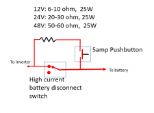
@Supervstech is talking about a circuit like this:
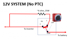
This circuit is documented in this resource:

Inverter Disconnect Switch with Precharge
To get the paper, click on the orange button at the top of this page. This circuit is designed as a disconnect switch that allows the user to pre-charge the inverter capacitors before turning the switch completely on. 26 June 2020 update: At...
It was simpler, just a switch and a resistor around the breaker.@HaldorEE is talking about a circuit like this:
View attachment 35647
@Supervstech is talking about a circuit like this:
View attachment 35648
This circuit is documented in this resource:

Inverter Disconnect Switch with Precharge
To get the paper, click on the orange button at the top of this page. This circuit is designed as a disconnect switch that allows the user to pre-charge the inverter capacitors before turning the switch completely on. 26 June 2020 update: At...diysolarforum.com
Maast
Compulsive Tinkerer
Correction, its a 10k resistor, can't edit my post.I'm using a 40k ohm resistor continually bridging the contactor, at 51v it only passes about .1millamp and according to the numbers it'll fill a inverters capacitors in about 25 mins but not allow the voltage to rise enough to turn the inverter back on.
40 ohm at 10W is pretty ideal for a 12V system.
I am using an 82 ohm, 25W resistor with my 25.6V battery. And yes I know this is slightly overkill. I even have a heat sink for the resistor. People just don't have any idea hot resistors can get dissipating power.
For example, I was using this 1 ohm, 200W resistor as a load dump for a constant current battery capacity tester I am building.
First I tested at 15A and the resistor started to overhead (outgassing). That is with a heat sink and a fan. I am replacing it with a pair of identical resistors in series and mounting them on a water cooled plate. That is so I can handle 200W of power (resistors totally 400W rating, with water cooling).
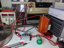
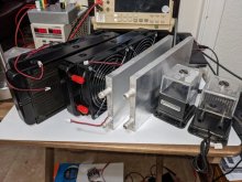
Obviously I don't need anything like this for the inverter precharge, but perhaps that gives you some insight into what I mean when I say something is conservatively engineered.
If I am going to do this in my RV system, then I want to be able to dead short the resistor continuously without causing a problem. Don't forget that circuit is bypassing the circuit breaker. I don't want something in my electrical closet catching fire one night because I didn't do my part.
I am using an 82 ohm, 25W resistor with my 25.6V battery. And yes I know this is slightly overkill. I even have a heat sink for the resistor. People just don't have any idea hot resistors can get dissipating power.
For example, I was using this 1 ohm, 200W resistor as a load dump for a constant current battery capacity tester I am building.
First I tested at 15A and the resistor started to overhead (outgassing). That is with a heat sink and a fan. I am replacing it with a pair of identical resistors in series and mounting them on a water cooled plate. That is so I can handle 200W of power (resistors totally 400W rating, with water cooling).


Obviously I don't need anything like this for the inverter precharge, but perhaps that gives you some insight into what I mean when I say something is conservatively engineered.
If I am going to do this in my RV system, then I want to be able to dead short the resistor continuously without causing a problem. Don't forget that circuit is bypassing the circuit breaker. I don't want something in my electrical closet catching fire one night because I didn't do my part.
Hedges
I See Electromagnetic Fields!
- Joined
- Mar 28, 2020
- Messages
- 20,436
40 ohm at 10W is pretty ideal for a 12V system.
I am using an 82 ohm, 25W resistor with my 25.6V battery. And yes I know this is slightly overkill. I even have a heat sink for the resistor. People just don't have any idea hot resistors can get dissipating power.
Resistors - Good if they have wattage rating >= V^2/R. In Haldor's example, 25.6^2/82 = 8W, so 25W is great. Overkill? Only slightly. No matter how big a capacitor bank being charged, it won't overheat.
What sort of RC time constant do you see with that?
One can get away with less wattage, but some resistors are better at withstanding an impulse than others.
We had 0402 current-sense resistors for an 0.5A load (very small value), and they kept blowing. Turned out to be current surge charging up a capacitor in the device, maybe it was a brushless fan or the like. I measured an 80A, 10 microsecond pulse when 24V was applied. A surge-rated resistor which happened to be 0603 was robust.
I wonder about too large a value, allowing inverter enough time that it tries to power up before you close the switch.
FilterGuy
Solar Engineering Consultant - EG4 and Consumers
My experience is that the inverter turns on but immediately goes into an under-voltage state.I wonder about too large a value, allowing inverter enough time that it tries to power up before you close the switch.
Similar threads
- Replies
- 7
- Views
- 588
- Replies
- 38
- Views
- 3K
- Replies
- 8
- Views
- 1K


