diy solar

diy solar

Inverter Disconnect with Pre-Charge

TAS CPA

New Member
Joined
Feb 16, 2021
Messages
95
In this basic layout, is using inverter disconnects with pre-charge in place of the basic battery disconnects OK? Is there a better location?

Sounds like if the pre-charge is before the battery fuses and the Lynx, I'll want to include the PTC Resistor. Sound correct? Don't recall who posted the inverter disconnect info, but it is awesome.

Thanks!
Beautiful Plan v11.jpg
 

Attachments

  • Inverter disconnect.pdf
    746 KB · Views: 27
I don't know what circuit is your precharge but I hooked mine off the main fuse panel, fused with a 15 or 20a fuse and the output from the button is wired to the inverter circuit breaker output. This way it is protected on the circuit for max amps and the circuit breaker is basically the switch to the inverter.

My main 300a master switch is mounted right above the red button resistor switch. Pretty hard to forget to precharge after throwing the master switch on. Then throw the inverter breaker.
 
Hmmm. Will have to spend some thinking time to be able to envision how that's wired up. Do you have a schematic posted here anywhere?

Thanks for all the help.
 
Hmmm. Will have to spend some thinking time to be able to envision how that's wired up. Do you have a schematic posted here anywhere?

Thanks for all the help.
No diagrams, don't know how to draw one. :)

I do everything in my head, I had to see a neurophysc doctor once and he told me that my cognitive memory and ability is up at genius level. One test he said no one ever gets it right but I had a perfect score until the very end and the last line I drew was ever so slightly crooked and he had to ding me a point. He admitted he knew I was just in a hurry. ;)

Basically, battery positive goes to the main fuse, then to the 300a master switch. From there to a main busbar, then a fuse panel is provided power from that busbar. Took one fuse slot and wired it to the push button with a 50 ohm resistor in the circuit, wire exiting push button goes to 24V circuit breaker output terminal that is hooked to Growatt.

Power to circuit breaker is from the positive busbar. I have circuit breaker open, hit the button a few times, then turn on circuit breaker. This only needs to be done if either the main disconnect switch is throw or the circuit breaker is opened.

Basically, the circuit is just like this one I found. https://diysolarforum.com/threads/m...ll-for-the-sw-4024-inverter.20426/post-238828

It doesn't matter where the resistor is in the circuit, it can be before or after the push button.
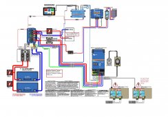
 
In this basic layout, is using inverter disconnects with pre-charge in place of the basic battery disconnects OK? Is there a better location?

Sounds like if the pre-charge is before the battery fuses and the Lynx, I'll want to include the PTC Resistor. Sound correct? Don't recall who posted the inverter disconnect info, but it is awesome.
The resistor gets wired up to the big red switch that is between the inverter and the Lynx. You only need the pre-charge resistor for the inverter. The whole idea is you only need the pre-charge if battery power to the inverter is disconnected at some point. The resistor is then used immediately before the power to the inverter is restored.

See Resource 'Inverter Disconnect Switch with Precharge' and apply that to the big red switch between the inverter and Lynx. The only change for the diagram you posted above is that you need to make sure the setup handles both positive wires between the switch and inverter.
 
No diagrams, don't know how to draw one. :)

I do everything in my head, I had to see a neurophysc doctor once and he told me that my cognitive memory and ability is up at genius level. One test he said no one ever gets it right but I had a perfect score until the very end and the last line I drew was ever so slightly crooked and he had to ding me a point. He admitted he knew I was just in a hurry. ;)

Basically, battery positive goes to the main fuse, then to the 300a master switch. From there to a main busbar, then a fuse panel is provided power from that busbar. Took one fuse slot and wired it to the push button with a 50 ohm resistor in the circuit, wire exiting push button goes to 24V circuit breaker output terminal that is hooked to Growatt.

Power to circuit breaker is from the positive busbar. I have circuit breaker open, hit the button a few times, then turn on circuit breaker. This only needs to be done if either the main disconnect switch is throw or the circuit breaker is opened.

Basically, the circuit is just like this one I found. https://diysolarforum.com/threads/m...ll-for-the-sw-4024-inverter.20426/post-238828

It doesn't matter where the resistor is in the circuit, it can be before or after the push button.
OK. Thanks for the detail of your flows. While your system config is different than mine, this at least lets me know where you have the pre-charge, and that will help me to decide how to implement that.

Again. Very helpful.

Thanks
 
The resistor gets wired up to the big red switch that is between the inverter and the Lynx. You only need the pre-charge resistor for the inverter. The whole idea is you only need the pre-charge if battery power to the inverter is disconnected at some point. The resistor is then used immediately before the power to the inverter is restored.

See Resource 'Inverter Disconnect Switch with Precharge' and apply that to the big red switch between the inverter and Lynx. The only change for the diagram you posted above is that you need to make sure the setup handles both positive wires between the switch and inverter.
Thanks. If doing it where I have the two red switches, was presuming that I'd need to set up the pre charge on both of them so either battery could be used first, but would only have to actually pre-charge once if both batteries were to be turned on. Does it work that way?
 
Thanks. If doing it where I have the two red switches, was presuming that I'd need to set up the pre charge on both of them so either battery could be used first, but would only have to actually pre-charge once if both batteries were to be turned on. Does it work that way?
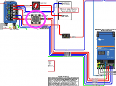
There's only one red (actually gray) switch between the inverter and Lynx. At least in the diagram you posted.
 
The switch circled in purple is where you apply the resistor.

PCRSwitch.png
 
There's only one red (actually gray) switch between the inverter and Lynx. At least in the diagram you posted.
OK, that was my confusion. If doing it between the Lynx and MultiPlus just pre charging one of those two feeds won't be enough? Both wires go to a common bus/input on the MultiPlus.
 
OK, that was my confusion. If doing it between the Lynx and MultiPlus just pre charging one of those two feeds won't be enough? Both wires go to a common bus/input on the MultiPlus.
Look at the link I provided in my first reply. Using that setup is what you need in place of the switch between the inverter and Lynx. As I stated in my first reply, just make sure the resistor inside the switch is connected so it applies to both wires leaving the switch. Once you look at the link I posted it will be fairly obvious.
 
One other thing to keep in mind with the schematic you posted. If the batteries are every disconnected, whether you remove a wire or turn off the switches next to the batteries, be sure you also turn off the switch between Lynx and inverter. That inverter switch must be in the off position before battery power is reconnected/switched back on. After power to the system is restored, then you use the inverter switch with the pre-charge setup to reconnect the inverter.

If battery power is disconnected but the inverter switch is left on and then battery power is restored, then the pre-charge circuit won't be used and there will be a big spark somewhere.
 
OK. Thanks for the detail of your flows. While your system config is different than mine, this at least lets me know where you have the pre-charge, and that will help me to decide how to implement that.

Again. Very helpful.

Thanks
If you have a disconnect switch, just put the precharge circuit from one terminal of the switch to the other.
 
Thanks. If doing it where I have the two red switches, was presuming that I'd need to set up the pre charge on both of them so either battery could be used first, but would only have to actually pre-charge once if both batteries were to be turned on. Does it work that way?
As long as the switch remains on, there is no need to precharge before turning the inverter on. It is only after a power disconnect to the inverter that any precharge is needed.

Examples are if you need to work on your battery and had turned off all power. Or you blow a main fuse or breaker and it disconnects power. Or you turn off the inverter power supply with your switch on the inverter power supply.
 
If you have a disconnect switch, just put the precharge circuit from one terminal of the switch to the other.
Yes, have a Blue Sea 3002 (500Amp continuous) switch and a 3 ohm 25watt resistor to wire in. Would 12awg be hefty enough for the wire in and out of the resistor? Doesn't seem like the amperage through that wire would be significant.
 
One other thing to keep in mind with the schematic you posted. If the batteries are every disconnected, whether you remove a wire or turn off the switches next to the batteries, be sure you also turn off the switch between Lynx and inverter. That inverter switch must be in the off position before battery power is reconnected/switched back on. After power to the system is restored, then you use the inverter switch with the pre-charge setup to reconnect the inverter.

If battery power is disconnected but the inverter switch is left on and then battery power is restored, then the pre-charge circuit won't be used and there will be a big spark somewhere.
All of this stuff would seem to benefit from an airline style checklist of all of the different startup and shutdown processes!
 
Yes, have a Blue Sea 3002 (500Amp continuous) switch and a 3 ohm 25watt resistor to wire in. Would 12awg be hefty enough for the wire in and out of the resistor? Doesn't seem like the amperage through that wire would be significant.
I used 18AWG wire for my pre-charge resistor. I've used it about 4 times, 5 seconds each time. No smoke yet.

All of this stuff would seem to benefit from an airline style checklist of all of the different startup and shutdown processes!
I have actually started an "Owner's Manual" for my cargo trail camper. It includes a bunch of checklists. This sort of electrical stuff needs several checklists.
 
Yes, have a Blue Sea 3002 (500Amp continuous) switch and a 3 ohm 25watt resistor to wire in. Would 12awg be hefty enough for the wire in and out of the resistor? Doesn't seem like the amperage through that wire would be significant.
Should be sufficient, you only press the button for a second. I just push mine a few times to ensure I don't get a spark that could weld the contacts of the breaker together.
 
Should be sufficient, you only press the button for a second. I just push mine a few times to ensure I don't get a spark that could weld the contacts of the breaker together.
I just hold down my button for 5 seconds and then turn on the inverter. Watch Will's video on the subject. He just touches the resistor to the terminal for a few seconds and then connects the wire. No need to "pulse" the button.
 
I just hold down my button for 5 seconds and then turn on the inverter. Watch Will's video on the subject. He just touches the resistor to the terminal for a few seconds and then connects the wire. No need to "pulse" the button.
Some say a second, some say 5 seconds. It's whatever works. I just hit mine a few times just to ensure I charged the caps to prevent any arc.

I think much depends on the resistor used, I used the 50 ohm in the original precharge thread.
 
Back
Top