Pholman
New Member
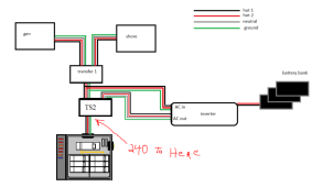
I have recently wired a new inverter to my RV system. Everything seems to work other than the power from the inverter. I have tested the output of the inverter and I am getting 240V AC out after switch 2. But, the control system does not turn on. It comes on with shore power, and transfers to Generator when the generator is on, but not when I only have the inverter on.

Because I have verified power is getting beyond the second switch, I am thinking the power management system does not like the power from the inverter, or there is a lead going to the first switch identifying which side of the switch is active.
I have tested the inverter without any AC to it, checks out fine. I have a reading of 115 between hot and neutral for both hot wires. I have 0 between ground and neutral. I have 238 between the two hots. However, I do not get any reading between the ground and the Hot leads. I am grounded to the chassis and checked and made sure it was metal to metal. All readings above are the same on the Load side of switch 2 when the inverter is running. Switch 2 is grounded to the chassis and another ground from the existing system.
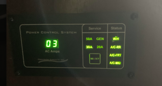
When plugged into shore power this is what I get at the PCS. When I turn on the generator, switch 1 transfer and the PCS switches to Gen power. No problems here!

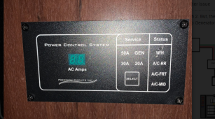
This is what I get with only the inverter on and 240 at the load side of switch 2. Same wire feeding the panel from the other two power sources.

My inverter is a Sun Gold Power 12 volt dual phase 4000 watt. I have been on with Tech support for the inverter and the power is good. Everything beyond what I have wired shows power. The only thing suspect to me is hot to the ground is not reading anything.
Transwitch I installed is a Go-Power TS-50
I think I am missing what is telling the PCS board what type of power is being provided, shore or generator. Is there something in the first switch picking up a signal?
Sorry for the long write-up. I am trying to provide anything I can think of to avoid back and forth here.

Because I have verified power is getting beyond the second switch, I am thinking the power management system does not like the power from the inverter, or there is a lead going to the first switch identifying which side of the switch is active.
I have tested the inverter without any AC to it, checks out fine. I have a reading of 115 between hot and neutral for both hot wires. I have 0 between ground and neutral. I have 238 between the two hots. However, I do not get any reading between the ground and the Hot leads. I am grounded to the chassis and checked and made sure it was metal to metal. All readings above are the same on the Load side of switch 2 when the inverter is running. Switch 2 is grounded to the chassis and another ground from the existing system.
When plugged into shore power this is what I get at the PCS. When I turn on the generator, switch 1 transfer and the PCS switches to Gen power. No problems here!

This is what I get with only the inverter on and 240 at the load side of switch 2. Same wire feeding the panel from the other two power sources.

My inverter is a Sun Gold Power 12 volt dual phase 4000 watt. I have been on with Tech support for the inverter and the power is good. Everything beyond what I have wired shows power. The only thing suspect to me is hot to the ground is not reading anything.
Transwitch I installed is a Go-Power TS-50
I think I am missing what is telling the PCS board what type of power is being provided, shore or generator. Is there something in the first switch picking up a signal?
Sorry for the long write-up. I am trying to provide anything I can think of to avoid back and forth here.


