diy solar

diy solar

Inverter with Limiter

I only mentioned AC-coupling to distinguish my new planned-for 2kW DC-coupled PV array from my existing 4kW Microinverters-based PV array, which is to code, on net metering, and which I don’t want to touch.
I don't know who issued your Permission to Operate was, but it is common in California PTOs to allow 1kW or 10 percent increase in output without permission. In the case of my Skybox I was able to program it to limit the DC coupled solar only to export 1kW.
The neutral is common to both phases so that should not be a problem. The question will be whether the chassis ground and the neutral are bonded and/or if the chassis is isolated. That you may have to check with a meter. Those are some of the things that UL certification more or less tests for.
I am based in California and my utility has told me that any change to my system, including replacing a damaged component and certainly capitalizing on the pre-authorized ‘10% or 1 kW, whichever is greater’ increase to my net meter system requires submission and approval first. If I am making changes that do not result in any change to the equipment exporting to they grid, that tell me they do not need to be involved.

I specifically inquired about a hybrid inverter that never exports power and was told need to involve e them and no need to seek permission as far as my NEM agreement.

On the neutral, I see it like you do but several internet ‘experts’ suggest that has been tried and will not work. I know that some 120V inverters are designed to be combined for split-phase capability, while others are not, so while I don’t fully understand the intricacies, I know enough not to take that capability for granted with these Chinese inverters.

The binding issue can usually be solved as long as you check for it. One mystery about these GTIL inverters is that fhey claim to ‘autodetect’ 240 or 120V and I don’t believe that is easy/possible. Some of those same Internet experts claim these inverters are 240V, full stop, and if that is the case, parallel connecting 2, one limited by L1 and the other limited by L2, then feeding that combined power into an Autotransformer, may be the most straightforward solution.

It may also be possible to series-connect 2 sensors into one larger inverter, though the Autotransformer would still be needed.
 
I specifically inquired about a hybrid inverter that never exports power and was told need to involve e them and no need to seek permission as far as my NEM agreement.
I have several systems, two with SCE and one with PG&E. I have replaced the inverters over the years on the SCE ones and increased the size of one of those by a kWh. My theory is it is easier to ask for forgiveness although I realize the penalty may throw me into NEM 2.0. I am selling the townhome under the relatively unmodified system so that will not be an issue.
My existing system with PG&E is now only temporary because with the proceeds of the townhome sale we will be buying a larger place and I will move the Skybox to that future home. The first thing I will do is get a GT system installed and then AC couple that to the Skybox. I may be forced to do that bootleg because of the new NEC battery UL requirements.
Our boats aren’t all that different. I’m in the Bay Area and was motivated to expand the solar for a planned-for EV as well as off-grid capability during fire season. Was all set to pull the trigger on a Magnum PAE and a full permitted install with UL listed components, but now we’re thinking we’re likely moving somewhere new within <5 years and I’m more focused on avoiding getting screwed by the new peak window as inexpensively as possible than I am on doing everything right for the long run.

I’m happy to hear you added a kW without issue with SCE, but NEM2.0 would end up costing me an additional $100/year in taxes versus NEM 1.0, so I don’t want to take any risk of violating my agreement...

Haven’t looked into the new NEC battery requirements but looked enough into doing a fully permitted battery install to understand it’s a showstopper on my budget and DIY / bootleg is the only way forward.

Some online sources have talked about a ‘tamper flag’ or some kind of warning being triggered in the smart meter if these zero-export solutions are not implemented correctly, so that’s something I absolutely want to avoid. The modest cost of an Autitransformer is a modest price to pay if it helps assure everything is kosher and is not detectable by the smart meter..,
 
I have several systems, two with SCE and one with PG&E. I have replaced the inverters over the years on the SCE ones and increased the size of one of those by a kWh. My theory is it is easier to ask for forgiveness although I realize the penalty may throw me into NEM 2.0. I am selling the townhome under the relatively unmodified system so that will not be an issue.
My existing system with PG&E is now only temporary because with the proceeds of the townhome sale we will be buying a larger place and I will move the Skybox to that future home. The first thing I will do is get a GT system installed and then AC couple that to the Skybox. I may be forced to do that bootleg because of the new NEC battery UL requirements.
I’ve been thinking more about this and would appreciate any insight from your experience.

My question reduces down to understanding whether smart meters separately monitor consumption on L1 and L2. Even though all the reporting is for total L1+L2 consumption, I feel like it’s only safe to assume that the utility is getting data on current consumed in each leg separately.

If that is the case, it seems to me that the only way to use current-limited inverters to offset consumption is to do it separately for each leg.

If I connect a sensor to L1, use it to generate an offsetting amount of 240V power, feed that into a step-down Autotransformer to 120V (L1, N) and then feed that into the panel through a breaker, current consumption on L1 will drop to 0A from the perspective of the smart meter (while consumption on L2 will continue unchanged).

Repeat that design with a second inverter/transformer limited by L2 and L2 consumption will also be reduced to zero.

If the inverters can generate 120V and can be stacked by bonding neutral to generate offsetting 240V current on both L1 and L2, the cost and complexity of adding the autotransformers can be skipped, but I’m skeptical that a 1000W 220/240V autodetect inverter is going to actually generate a full 1000W at 120V (since Current would need to be twice as high as it would be at 240V).

So I’m just seeing this approach as the only way to assure no current going out to the grid (equivalent to opening the main breaker).

I’ve seen diagrams where others are using L1+L2 current to generate offsetting 240V power, but if the load is unbalanced (let’s assume 100% load on L1, 0% load on L2), I believe there is going to be some generated current going out to the grid (L1 current reduced to 50% and L2 current -50% going out to the grid in this case).

Autotransformers are pretty inexpensive and reliable, so I’m thinking hanging up two with common neutral to create floating L2’, L1, N, L2, floating L1’ is the safest way to assure that none of the current being generated goes through the smart meter to the grid.

Anyone else understand how these smartmeters work well enough to comment?
 
‘Bonding neutral’ was a poor choice of words. Common neutral would have been better.

Neutral is bonded to ground in the main panel and no changes to that bond.
 
I would guess the Smart (or dumb) meter just combines measurements on various phases and uses combined watts to track watt-hours.

So long as only used for grid-tie, two 120V inverters would work happily, oblivious to each other. (Off-grid they need synchronization to produce valid split-phase.)
If each 120V inverter had its own current transformer on its own phase, one might curtail production while the other couldn't produce enough to zero.
I'm going to assume the current transformers include a resistor, turning the measured current into proportionate voltage (rather than potentially lethal voltage)
If the two current transformers had their outputs combined, either in series or in parallel, I would expect that to provide a signal both inverters could follow. However, the inverters may impose a bias voltage which is incompatible between them. I'd have to measure/experiment to see if that would work.

Putting each current transformer around both L1 and L2 (with a loop added to one of the Lx so field sums instead of cancelling) should do what you want, while keeping the current transformers electrically separated. All assuming that only sum of power on legs, not individual power, are actually tracked.
 
Anyone else understand how these smartmeters work well enough to comment?
I saw my meter briefly when my installer installed my new service panel. The meter has no neutral, it only measures the 240 volt current and translates that to Watts and transmits data in kWhs via Zigbee. As far as I know it has no investigative ability. I do not think it is something you need to worry about. The concept that I have heard repeatedly as far as the utilities like PG&E and SCE is that we can do anything we want behind the meter as long as we do not backfeed the grid. The meter does not know what your PTO says as far as any limit on production. That would have to reside at the central office where the billing is done.
The flag you are referring to in an earlier post is probably the seal that the utility put on that part of the service panel to prevent access to the lugs that bring power to the panel. I needed to put CT clamps on those conductors because it was not possible to put them on anywhere on my side of the meter. I have been told that I own the service panel and I know of no law that says I cannot access it for the purpose of attaching CT clamps.
 
I would guess the Smart (or dumb) meter just combines measurements on various phases and uses combined watts to track watt-hours.

So long as only used for grid-tie, two 120V inverters would work happily, oblivious to each other. (Off-grid they need synchronization to produce valid split-phase.)
If each 120V inverter had its own current transformer on its own phase, one might curtail production while the other couldn't produce enough to zero.
I'm going to assume the current transformers include a resistor, turning the measured current into proportionate voltage (rather than potentially lethal voltage)
If the two current transformers had their outputs combined, either in series or in parallel, I would expect that to provide a signal both inverters could follow. However, the inverters may impose a bias voltage which is incompatible between them. I'd have to measure/experiment to see if that would work.

Putting each current transformer around both L1 and L2 (with a loop added to one of the Lx so field sums instead of cancelling) should do what you want, while keeping the current transformers electrically separated. All assuming that only sum of power on legs, not individual power, are actually tracked.
Appreciate these inputs.

If the meters combine measurements from the two phases as you suggest, then having +50% on one phase and -50% on the other (as per my extreme example) looks like zero consumption to the meter, so that should work fine.

The meters already have separate sensors and so until I have confirmation those sensor outputs are combined in series internally in the manner you’ve outlined (sum fields), it’s just too easy for the smart meter to make visible to the utility that current is being consumed on one leg and output to the grid on the other. I’ve heard about folks screwing around with these net zero inverters setting off tamper flags with their utilities and don’t want to risk that.

Not worried about one 120V (or 240V) maxing our and being unable to fully zero out one leg while the other inverter is underutilized. This still offsets much of consumption and is invisible to the smart meter and circuits can always be moved between phases to better-balance consumption.

I’m not sure what you are referring to as far as resistors in the transformers. From what I’ve understood, Autotransformers just convert single-phase 240V to single-phase 120V (or vica-versa).

So to combine two separate out-of-phase 240V inverters through two Autotransformers, unused L2’ leg of the L1 inverter is left floating (connected to the L2 input on the L1 Autotransformer), the L1 leg of the L1 inverter passes through the L1 input/output of the L1 Autotransformer into an L1 breaker on the panel, the Neutral output of the L1 Autotransformer is connected to panel Neutral as well as the Neutral output of the L2 Autotransformer, the L2 leg of the L2 inverter passes through the L2 input/output of the L2 Autotransformer while the unused L1’ leg of the L2 inverter is left floating (connected to the L1 input of the L2 Autotransformer).

Both Autotransformers need to have casings grounded without any bonds to neutral and Autotransformer Neutrals need to be connected to mains neutral (and hence together), while both 240V inverters also need to be grounded without any bonds.

I don’t see any bias voltages to worry about - the connections to system neutral is probably the trickiest item but I think it will just balance through the bond to ground exactly as it does with any imbalance on L1 versus L2 consumption for any household with 2-phase 240V power.

Done this way, I think that current on both L1 and L2 phases at the smart meter will be zero, so net zero on each independent leg (and pseudo-independence from the grid,at least as far as current generation to the grid).

Any further thoughts appreciated.
 
I saw my meter briefly when my installer installed my new service panel. The meter has no neutral, it only measures the 240 volt current and translates that to Watts and transmits data in kWhs via Zigbee. As far as I know it has no investigative ability. I do not think it is something you need to worry about. The concept that I have heard repeatedly as far as the utilities like PG&E and SCE is that we can do anything we want behind the meter as long as we do not backfeed the grid. The meter does not know what your PTO says as far as any limit on production. That would have to reside at the central office where the billing is done.
The flag you are referring to in an earlier post is probably the seal that the utility put on that part of the service panel to prevent access to the lugs that bring power to the panel. I needed to put CT clamps on those conductors because it was not possible to put them on anywhere on my side of the meter. I have been told that I own the service panel and I know of no law that says I cannot access it for the purpose of attaching CT clamps.

No, the tamper flags being ‘tripped’ have nothing to do with physical disturbance of the meter or the seal. They are electronically generated messsages within the utility to go inspect that customer because something fishy is going on.

I understand that the meter has no neutral, but that is irrelevant. I’m not sure how these smart meters sense current, but the fact that a current-limit clamp does it with a low-cost coil around an individual phase makes it trivial for the smart meters to do it in the same way. Unless there is a single sensor being used or 2 separate sensors are being wired in series (so there is only a single signal being input), it’s just too easy for the smart meter to have additional information beyond what is tracked and reported (which can be used to generate a tamper message).

I’ve seen what my microinverter supplier has been able to do to my microinverters through the Internet - beyond checking out all sorts of internal statistics their monitor does not show me, they changed parameters and even upgraded FW, all through the power grid and from their remote console connected via internet.

It’s just too easy, ‘Smart’ technology delivers far more capability than most realize, and for a few $hundred for a couple Autotransformers, I’d rather have the peace of mind that none of the current I am generating is going out to the grid (which is better for the grid, by the way).
 
I’m not sure what you are referring to as far as resistors in the transformers. From what I’ve understood, Autotransformers just convert single-phase 240V to single-phase 120V (or vica-versa).

Yes, auto transformers or isolation transformers can be used to convert between 240V and 120/240V for power.

I was referring to current transformers used for instrumentation, to create a small analog signal representing a large current.
I can use two current transformers so one measurement represents power on two phases (so long as voltages aren't too unbalanced.)
It would be if you had two separate devices (e.g. a 120V inverter on each phase) that wiring them to the same sensor(s) might not work.

If your PV generation is generally smaller than consumption, you wouldn't lose much by curtailing production when one phase approaches zero current.

It would also be possible for a utility meter to measure VA not watts, in which case current through each phase would count toward your total bill regardless if whether is was consumption or production. But I don't think that is the case. Obviously bidirectional meters for net metering don't simply measure VA.
I’ve seen wiring diagrams where two sensors are connected in Series so that the outputs (currents) add, so a single pair of sensors can be used to limit a single inverter to combined 240V power.

I’m not interested in this because I can’t find any straightforward way to drive both L1 and L2 to zero current in the case of unbalanced loads.

My system will be driven off of battery power, not PV. PV will be used to charge the battery while the sun is high and $/kW is low. Once sun has gone down and $/kW has gone up (doubled), I want to use the energy stored in the battery to drive net consumption from the point of the utility to zero.

I’m already on net metering, so no concerns about being charged for generated current being output. It’s more current being generated (on either phase) after the sun has gone down that I’m worried about.

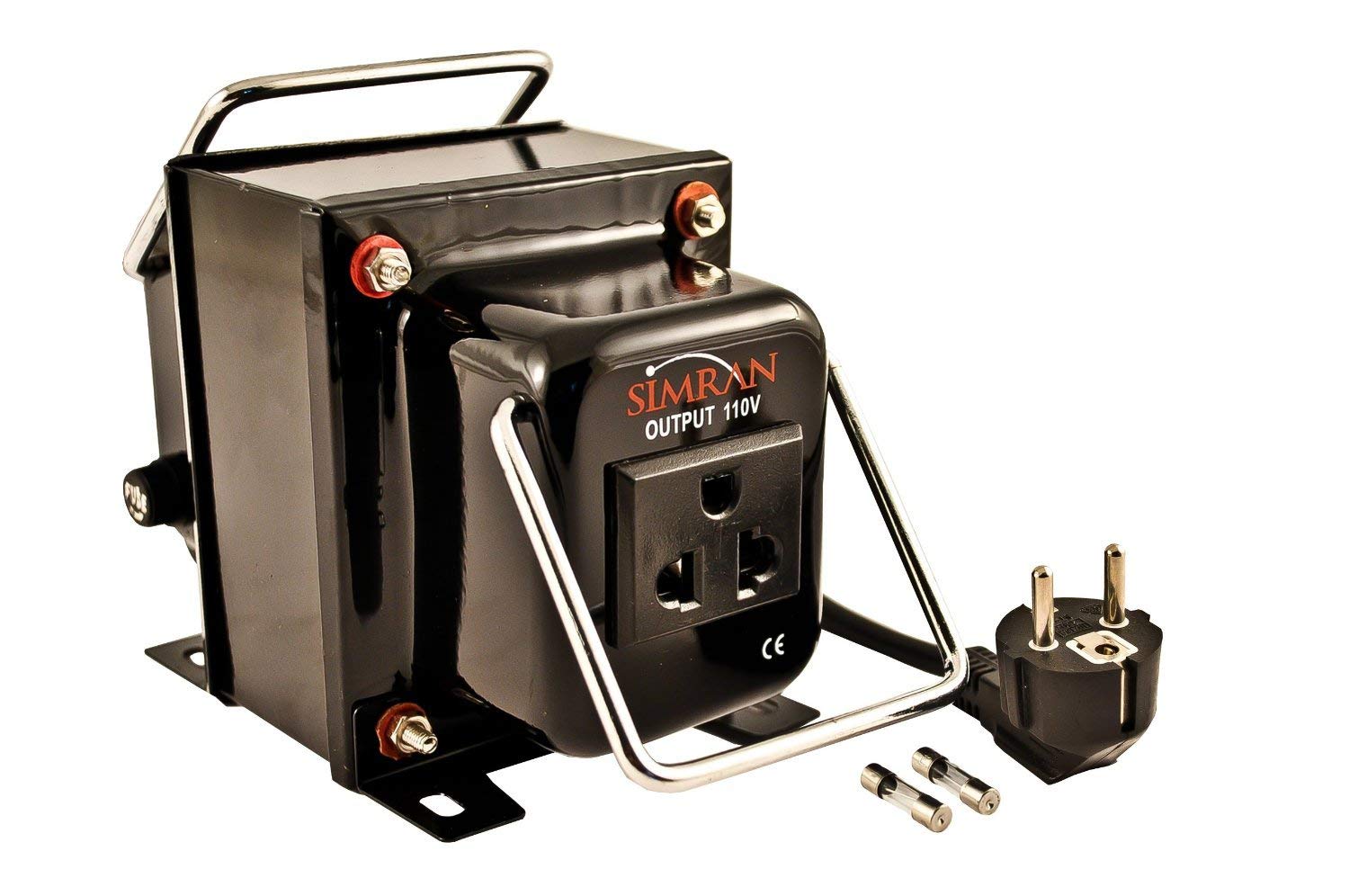
Here’s an example of the kind of Autotransformer I’m thinking of using ($70):
 
My system will be driven off of battery power, not PV. PV will be used to charge the battery while the sun is high and $/kW is low. Once sun has gone down and $/kW has gone up (doubled), I want to use the energy stored in the battery to drive net consumption from the point of the utility to zero.
"I am based in California"

Only doubled? Mine triples.

What is your battery cost, $/kWh?
Most batteries I've seen cost at least as much as the spread between my low-time and high-time rates.
Some DIY have been reported at about $0.05/kWh, however.

I put PV + GT inverter at $0.025/kWh, maybe $0.05/kWh for complete system including mounting racks.
So I see it as more cost effective to deliver 3 kWh in the morning, earning a credit that I traded for 1 kWh in the evening.
Better deal than buying batteries according to my math.

What do you think?
Today, most of my consumption costs me $0.20/kWh while most of my solar generation is credited at $0.40/kWh.

By 2022, those numbers will have switched (at least for the 4 highest-generating months of the year).

I got 8 280Ah LiFePO4 cells for $93.59 each (with shipping), so $104.45/kWh.

Assuming I can time shift the full
"I am based in California"

Only doubled? Mine triples.

What is your battery cost, $/kWh?
Most batteries I've seen cost at least as much as the spread between my low-time and high-time rates.
Some DIY have been reported at about $0.05/kWh, however.

I put PV + GT inverter at $0.025/kWh, maybe $0.05/kWh for complete system including mounting racks.
So I see it as more cost effective to deliver 3 kWh in the morning, earning a credit that I traded for 1 kWh in the evening.
Better deal than buying batteries according to my math.

What do you think?
Today, most of my consumption costs me $0.20/kWh while most of my solar generation is credited at $0.40/kWh.

By 2022, those numbers will have switched (at least for the 4 highest-generating months of the year).

I got 8 280Ah LiFePO4 cells for $93.59 each (with shipping), so $104.45/kWh.

Assuming I can time shift the full 7kW from $0.20/kWh part of the day to $0.40/kWh peak period in the evening for 120 days a year, I’ll be saving $168/year.

So it’ll take me 4.5 years to break-even on the battery, but I needed it anyway for backup during fire outages.

I spoke with my utility and those conversations convinced me to leave my existing grandfathered grid-tied PV system as-is.
 
"I am based in California"

Only doubled? Mine triples.

What is your battery cost, $/kWh?
Most batteries I've seen cost at least as much as the spread between my low-time and high-time rates.
Some DIY have been reported at about $0.05/kWh, however.

I put PV + GT inverter at $0.025/kWh, maybe $0.05/kWh for complete system including mounting racks.
So I see it as more cost effective to deliver 3 kWh in the morning, earning a credit that I traded for 1 kWh in the evening.
Better deal than buying batteries according to my math.

What do you think?
Also, I must not be understanding how you are calculating $/kWh.

For my new off-grid solar install, I’m looking to install 2kW of panels for $800 and full install including racking, wiring, and MPPT charge controllers totaling to $1200-1300 all-in, which is $0.60-0.65 per Watt (not including my labor).

Using my existing 4kW system to estimate production, I’m expecting ~2500kWh of production annually from this 2kW array, meaning $0.48-0.52 per kWh of production on an annualized basis.

At $0.20/kWh, that means the array will break-even in ~2.5 years.

I must be doing something different I’m how I look at this, because I cannot understand how you get to numbers like $0.025 or $0.05/kWh...
 
Assuming I can time shift the full 7kW from $0.20/kWh part of the day to $0.40/kWh peak period in the evening for 120 days a year, I’ll be saving $168/year.
If I understand your rate structure, you are going to charge your batteries at $.20/kWh and discharge to reduce consumption at $0.40 by 7kWh. Without taking into account any inverter overhead this will save you 840 kWh during that 120 day peak period. Your net cost of the energy will be (840 x $0.20) $168. In addition, by taking load off the grid from 5PM to 9PM, you will be helping the grid because that when the grid is most stressed.

If you get an EV rate you can bring that cost down to maybe as low as $0.15/kWhr.
Yeah, that’s the idea (in addition to having that generation and battery capacity available for backup when the grid shuts down for up to a week at a time due to high winds and fire danger).

EV rate saves me some on off-peak cost but forces me off of NEM1 onto NEM2, which means ~10% taxes owed on the entire 5000 kWh I currently shove into the grid and consume back later (meaning an additional ~$100/year).

Best solution for me looks to be use new DC-coupled solar array to charge batteries and offset peak consumption while reserving credit from generated AC-coupled grid-tied solar to cover cost of charging an EV (even at $0.20/kWh each way).

Oh, and by 2022, it’ll be 6pm to 11pm, not 5pm to 9pm ;).
 
At $0.20/kWh, that means the array will break-even in ~2.5 years.

I must be doing something different I’m how I look at this, because I cannot understand how you get to numbers like $0.025 or $0.05/kWh...
$0.20/kWh over 2.5 years,
Or amortized over 10 years, you will have generated power for $0.05/kWh

Same figure I got.

PV panels ought to last 25 to 40 years, some degradation in output.
Inverter ought to last 10 to 20 years. If 20, power is free the second 10, or amortized over 20 cost went down to $0.025 (by then time value of money really counts.)
If you do have to replace the inverter, that'll amortize out to $0.01/kWh for the second 10 years.

Very competitive with grid power now.
What I put in 15 years ago cost me $8/watt installed, $4/watt after 50% rebate. Amortized over 15 years maybe that was $0.20/kWh, break-even with utility.
 
EV rate saves me some on off-peak cost but forces me off of NEM1 onto NEM2,
I have never heard of that before. I have two properties on NEM 1.0 with SCE. The only thing that can kick you off NEM 1.0 is increasing your solar capacity. The EV rate is a tariff and you are free to change tariffs within a NEM agreement
 
Oh, and by 2022, it’ll be 6pm to 11pm, not 5pm to 9pm ;).

Pffft!

The "Duck's Back" curve is a lie.
The actual power consumption curve is high mid afternoon.
Only by taking <all consumption> and subtracting <PV production from people without political clout> can a curve be produced that shows PV is sometimes worth less that zero, no demand mid afternoon, and high demand early evening.

Sure, it may cost $100k to spin up a peaker plant late afternoon for the Duck's Back. But if it wasn't for us, would have had to do that anyway, just earlier in the day. We reduced the amount of natural gas which had to be burned.

I want to call a solar strike. Some hot summer afternoon at 2:30 PM, we all shut off our inverters. And we don't turn them back on until a new pricing schedule has been negotiated, crediting us for our surplus based on what PG&E had to pay to buy that power from another source.
 
Back
Top