diy solar

diy solar

Is it possible to use two different inverters on the same offgrid system?

Yup

New Member
Joined
Sep 26, 2022
Messages
6
Hi everyone. I'm a newbie who currently has a EG4 6000ex and a set of 48V LifePower batteries coming from SS. While waiting, I made the mistake of looking on craigslist and seeing some Victron equipment for sale at a big discount from a guy parting out his RV system. Now I have a MultiPlus-II 48/3000/35-50 120V, Lynx Distributor, and SmartShunt sitting in the garage waiting to be used.

My initial intent was to create a small off grid system at my home that was capable of L2 charging an EV and/or running an A/C unit like in one of Will Prowse's videos. However, after seeing one of Will's latest video with the 6000ex, I'm realizing that high idle consumption of the unit wouldn't make it the ideal choice for low consumption loads when not running the EV charger or A/C.

My questions to you all: Is it possible to use both the 6000ex (to run 240V loads) and Multiplus (for smaller loads) on the same battery bank without ruining either inverter? Can I connect them both on the same subpanel while only using one inverter at a time? Or...since I'd will be using the solar controller function of the 6000ex, could I piggyback it to the Multiplus by connecting the 6000ex AC output to the Multiplus AC input? Are there any options? Thank you. I'll appreciate any input.
 
The way I have my dual inverters set up is by having a transfer switch that can switch between them (a 6kW low frequency MUST inverter and a Multiplus II 3kVA). They can both run at the same time, just only one is switched to the house at any given time. The large low frequency inverter is in addition connected to a separate circuit for future EV charging, independent of the transfer switch position. They can also both function as a charger from a generator output; in practice I use the MUST as a charger when needed while the Multiplus powers the house - no pass-through from the generator to the house that way.
 
The way I have my dual inverters set up is by having a transfer switch that can switch between them (a 6kW low frequency MUST inverter and a Multiplus II 3kVA). They can both run at the same time, just only one is switched to the house at any given time. The large low frequency inverter is in addition connected to a separate circuit for future EV charging, independent of the transfer switch position. They can also both function as a charger from a generator output; in practice I use the MUST as a charger when needed while the Multiplus powers the house - no pass-through from the generator to the house that way.
Thanks for the reply! Using a transfer switch is an option I haven't considered simply due to budget restraints related to my impulse buy in the original post.

Do you have a detailed explanation of your setup? I'd love to see it. I checked out the links on your signature but didn't see what you were explaining. Are both inverters drawing power from the same batteries? If so, how are they connected? simple busbars? Thanks again
 
I have not had time yet to make a complete overview of the system, but to answer your question: both inverters are connected to the same batteries, to the same bus bar. They both have a fuse and a disconnect switch at the inverter. There is no issue doing this - the only thing you can not do is have their outputs connected together at any time because they're not in phase - hence the transfer switch. You don't need an automatic one, just one that prevents both outputs from being connected at the same time.
 
Just to point out, a manual transfer switch is very cheap. The automatic ones are much more expensive. A manual one is some people’s daily lunch expense.

You can hook two inverters to the same battery bank. In fact, my two Growatt inverters operating in parallel don’t even really coordinate their battery charging/draining activities, so even matching & paralleled inverters are functioning more like mismatched inverters than you might think, when it comes to the batteries anyway.

You could hook the larger inverter to the smaller inverter’s ac input, but i dont see the benefit in this case. What MIGHT be helpful is letting the large inverter run in an eco mode if that plays nice with the ev charger and ac.
 
Last edited:
If one inverter has a grid tie capacity, you could perhaps use it to supplement the "grid" that is actually created by your other inverter. Just have to ensure it doesn't try to export anything and voltage limits are set.
 
Not sure if this helps, but in Will's recent video about the EG4 6000EX, he talks about using two inverters (one with low idle) because the idle draw on the EG4 is so high.

 
I suspect it might be possible to feed the AC output of one converter into the input of a second converter.
 
That is absolutely possible to do. The question becomes, how to automate the interaction?

In theory it would be nice to have a small inverter with a small idle draw, that has an internal transfer switch, and hook the larger inverter with the larger idle draw to that transfer switch aka AC input. Idea is you only use the less efficient inverter when you need high power. Thing about it is the larger inverter would have to stay on for the smaller inverter to see it and transfer over to it during overload (overload for the small/efficient one). At that point you're running BOTH inverters all the time, which defeats the purpose.

Some inverters have an eco mode that turns the inverter output off and 'checks for load' exceeding something like 30w or something like that, at which point it reactivates. What is not clear to me is: if you hook the larger inverter in eco mode (for low standby consumption) to the AC input of the smaller inverter so that the small one will bypass to the large one under heavy loads, how would the small one recognize the large one as a 'live circuit' for it to switch over to if the inverter isn't putting 120v on that input at the time? As far as i know, inverters with transfer switches sync their frequency and phasing to whatever is detected on the AC input to make the transition seamless/harmless. If there is no waveform on the ac input, then even if the large inverter could come out of standby quick enough to accept the load that is being handed to it, i don't know if the small inverter could frequency shift its output quick enough to make the handover 'seamless', and that's IF it did the handover at all since it wouldn't think anything was connected to the ac input in the first place!

So what am i missing? Is there some other way to hook the two things together that allows for the low idle draw of the small inverter, while also being able to switch to the larger inverter, without manual intervention?
 
Crazy thought from fantasy land... would something like this work to minimize idle draw? Hook up both inverters independently to the same battery and set the larger one to ECO mode with a high threshold (assuming it is programmable). Most of the time, the load will be too small to trigger it. If you kick in a heavy load, the larger inverter would drop out of ECO mode, and for a time, both inverters would draw power from the batteries and supply it to the load. If the load gets too high for the smaller inverter, it's overload protection would kick in, and the larger inverter would handle the load alone. After the load drops back down to normal levels, the smaller inverter would kick back in and the larger one would go back into ECO mode.

Is something like that possible?
 
That is absolutely possible to do. The question becomes, how to automate the interaction?

In theory it would be nice to have a small inverter with a small idle draw, that has an internal transfer switch, and hook the larger inverter with the larger idle draw to that transfer switch aka AC input. Idea is you only use the less efficient inverter when you need high power. Thing about it is the larger inverter would have to stay on for the smaller inverter to see it and transfer over to it during overload (overload for the small/efficient one). At that point you're running BOTH inverters all the time, which defeats the purpose.

Some inverters have an eco mode that turns the inverter output off and 'checks for load' exceeding something like 30w or something like that, at which point it reactivates. What is not clear to me is: if you hook the larger inverter in eco mode (for low standby consumption) to the AC input of the smaller inverter so that the small one will bypass to the large one under heavy loads, how would the small one recognize the large one as a 'live circuit' for it to switch over to if the inverter isn't putting 120v on that input at the time? As far as i know, inverters with transfer switches sync their frequency and phasing to whatever is detected on the AC input to make the transition seamless/harmless. If there is no waveform on the ac input, then even if the large inverter could come out of standby quick enough to accept the load that is being handed to it, i don't know if the small inverter could frequency shift its output quick enough to make the handover 'seamless', and that's IF it did the handover at all since it wouldn't think anything was connected to the ac input in the first place!

So what am i missing? Is there some other way to hook the two things together that allows for the low idle draw of the small inverter, while also being able to switch to the larger inverter, without manual intervention?
I see that you were writing this at the same time that I was writing my similar (but less knowledgeable) post.
 
Crazy thought from fantasy land... would something like this work to minimize idle draw? Hook up both inverters independently to the same battery and set the larger one to ECO mode with a high threshold (assuming it is programmable). Most of the time, the load will be too small to trigger it. If you kick in a heavy load, the larger inverter would drop out of ECO mode, and for a time, both inverters would draw power from the batteries and supply it to the load. If the load gets too high for the smaller inverter, it's overload protection would kick in, and the larger inverter would handle the load alone. After the load drops back down to normal levels, the smaller inverter would kick back in and the larger one would go back into ECO mode.

Is something like that possible?

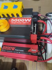
I exactly have this idea, not wired up yet. I also have a 2200w small Chinese inverter alongside my 5k. My PC loves it unilike the 5k :LOL:

Also doubles as backup.
 
I exactly have this idea, not wired up yet. I also have a 2200w small Chinese inverter alongside my 5k. My PC loves it unilike the 5k :LOL:

Also doubles as backup.
Please, please give it a try and let me know how it goes!
 
Crazy thought from fantasy land... would something like this work to minimize idle draw? Hook up both inverters independently to the same battery and set the larger one to ECO mode with a high threshold (assuming it is programmable). Most of the time, the load will be too small to trigger it. If you kick in a heavy load, the larger inverter would drop out of ECO mode, and for a time, both inverters would draw power from the batteries and supply it to the load. If the load gets too high for the smaller inverter, it's overload protection would kick in, and the larger inverter would handle the load alone. After the load drops back down to normal levels, the smaller inverter would kick back in and the larger one would go back into ECO mode.

Is something like that possible?
You can't connect the output of two inverters together, unless they are designed to do so (stackable).
 
You can do that with Victrons. The Off Grid Garage on YouTube shows setting up one Phoenix inverter that feeds it's power to a Multiplus. He shows how he configured the Multiplus to turn on the Phoenix after the Multiplus has a sustained AC load of 1000W or more for over 10s then it turns on the Phoenix. When load drops below 1000W the Phoenix turns back off. No extra equipment needed (besides some wires) since the hardware has this ability built-in.
 
Deleted - duplicate of OffGridGarage Series Multiplus and Phoenix.
 
Last edited:
You can do that with Victrons. The Off Grid Garage on YouTube shows setting up one Phoenix inverter that feeds it's power to a Multiplus. He shows how he configured the Multiplus to turn on the Phoenix after the Multiplus has a sustained AC load of 1000W or more for over 10s then it turns on the Phoenix. When load drops below 1000W the Phoenix turns back off. No extra equipment needed (besides some wires) since the hardware has this ability built-in.
His solar electrician was impressed once he explained how the configuration worked.
 
Andy has a very cool setup. I enjoyed watching his build.
Several inverters are stackable.
Growatt
MPP
EG4
And others
 
Back
Top