diy solar

diy solar

Is my build correct before I connect

reimanny

New Member
Joined
Aug 19, 2021
Messages
11
Hello, I'm new here. I read through many threads and now I'm a member myself.
I have 36 panels on the roof and have three hybrid inverters in my basement.
I want to make a 48 V system.

I attached my build as a .png. One without the BMS/ Balancer and the other with.
I'm this ok or will I short everything?

Blue cable from BMS is B-.
Black cable from BMS is P-.
Fuse is a 300 A.
Hybrid Inverters have 5 KW each.


Thanks in advance. :)

If you still have any questions please ask me. :)
 

Attachments

  • Batteries without BMS.png
    Batteries without BMS.png
    205.2 KB · Views: 26
  • Batteries with BMS.png
    Batteries with BMS.png
    438.6 KB · Views: 25
Last edited:
Hello, I'm new here. I read through many threads and now I'm a member myself.
I have 36 panels on the roof and have three hybrid inverters in my basement.
I want to make a 48 V system.

I attached my build as a .png. One without the BMS/ Balancer and the other with.
I'm this ok or will I short everything?

Blue cable from BMS is B-.
Black cable from BMS is P-.
Fuse is a 300 A.
Hybrid Inverters have 5 KW each.


Thanks in advance. :)

Hi !

I suggest to fuse both cables. Not only the +

Batteries in 4p16s config. Not ideal. BMS will see only average of 4 cell V.
Much better and reliable is a 16s4p config. Where you have 4 times parallel the 16 cells series pack.
That needs 4 BMS, 4 (x2) fuse, 4 disconnect switch (disconnect both + and -)

Except that for the 4p16s setup the cabling plan looks good.
And do not forget to precharge the resistors in the inverters :)
 
Last edited:
Hi, thanks really much for the help and answer. :)

Is it too bad to go with the 4p16s config?

300 A is enough or should it be less?

Not as safe as going with a 16s4p. In this config all cells are monitored.
If one row disconnects then you have 3 more that is still working. Also you can physically separate the parallel strings.

At the 300A I am not sure. How big are your cells? 280-310Ah ?
3 inverter 5kW = 15 kW .... /48V = 312A That is the max continuous the inverters can use. Even 1,5x that amount for short time.

Also if you make a 16s4p then you need 4x2 fuse.
The 312A is comming from 4 string ... usually 78A per string.
But even with 2 string down your setup could work, so 78 x 2 = 156A
For the 16s4p I would use 4x2 160A fuses


Should I fuse the Minus from the battery to the distributor or the Minus from the first battery to the BMS?
The fuse is best used after the BMS.


How do I precharge the resistors in the inverters? :s
Do you have a good tutorial flying around?


Hi !

I suggest to fuse both cables. Not only the +

Batteries in 4p16s config. Not ideal. BMS will see only average of 4 cell V.
Much better and reliable is a 16s4p config. Where you have 4 times parallel the 16 cells series pack.
That needs 4 BMS, 4 (x2) fuse, 4 disconnect switch (disconnect both + and -)

Except that for the 4p16s setup the cabling plan looks good.
And do not forget to precharge the resistors in the inverters :)

Hi, thanks really much for the help and answer. :)

Is it too bad to go with the 4p16s config?

300 A is enough or should it be less?
Should I fuse the Minus from the battery to the distributor or the Minus from the first battery to the BMS?

How do I precharge the resistors in the inverters? :s
Do you have a good tutorial flying around?

Thanks again. :)
 
Not as safe as going with a 16s4p. In this config all cells are monitored.
If one row disconnects then you have 3 more that is still working. Also you can physically separate the parallel strings.
Ah, ok.

At the 300A I am not sure. How big are your cells? 280-310Ah ?
3 inverter 5kW = 15 kW .... /48V = 312A That is the max continuous the inverters can use. Even 1,5x that amount for short time.
We have 280 Ah, sorry didn't mention that.

The fuse is best used after the BMS.
So then I use it between the first battery and the BMS or I'm wrong with that? :s


Thanks for the videos and explanations. :)
 
We have 280 Ah, sorry didn't mention that.
I use it too ;)

So then I use it between the first battery and the BMS or I'm wrong with that? :s
Its place is after the BMS, before the common busbar :)


Also after fuse it is good if you use shunt based meter to know the SoC of your battery.
If 4 in parallel then ... hmmm can be one for the whole battery bank, or can be 4 so one for every battery string.
 
Hi !

I suggest to fuse both cables. Not only the +

Batteries in 4p16s config. Not ideal. BMS will see only average of 4 cell V.
Much better and reliable is a 16s4p config. Where you have 4 times parallel the 16 cells series pack.
That needs 4 BMS, 4 (x2) fuse, 4 disconnect switch (disconnect both + and -)

Except that for the 4p16s setup the cabling plan looks good.
And do not forget to precharge the resistors in the inverters :)

The bms will not see an average of the 4 cells, the 4 cells instead equal each other other out therefore each having the same voltage. The bms sees them as one cell
 
The bms will not see an average of the 4 cells, the 4 cells instead equal each other other out therefore each having the same voltage. The bms sees them as one cell

Test it :)
Andy did not believed me when I wrote that a 30% and a 70% SoC cell will not balance each other out parallel ... was thinking there will be huge A flowing. But no. As I measured on a 10-20% SoC difference there is almost no A flowing (before under 3A, fast declining).
Here is Andy's test with a ca 10 and 90% SoC cells.


Even in the top charge phase it is a problem.
A good example are the simple active balancers (no super capacitor). They can not equalize efficiently with low V difference too.

Because of the flat charge and discharge curves.
And because the 3 Voltage values of the cell on the same SoC: relax V and discharging+charging V based on A.
 
I must clarify. The voltages of the 4 cells will be the same. The SOC of each cell can still be very different. Voltage is not a direct indicator of a cells capacity. It’s best if the 4 cells on 1 bms lead are tested to be the same capacity when at the same voltage. With Lifepo4 cells their capacity can vary greatly when they are the same voltage, more so if they are not matched and batched. Also do to the flat discharge curves mrzed001 mentioned. So I might agree that with Lifepo4 cells or cells that have varying capacities at the same voltage, a separate bms should be used.

I am not using Lifepo4. I’m using EV cells that are matched/batched very well. The cells never vary by more than 25mv. I have 6 cells (one from each battery) going to one bms cell sense wire. When I disconnect the connectors between each battery, and test the voltage of the cells, each cell that was sensed by the same bms lead has exactly the same voltage. And exactly the same a day later when retested.
 
Last edited:
Test it :)
Andy did not believed me when I wrote that a 30% and a 70% SoC cell will not balance each other out parallel ... was thinking there will be huge A flowing. But no. As I measured on a 10-20% SoC difference there is almost no A flowing (before under 3A, fast declining).
Here is Andy's test with a ca 10 and 90% SoC cells.


Even in the top charge phase it is a problem.
A good example are the simple active balancers (no super capacitor). They can not equalize efficiently with low V difference too.

Because of the flat charge and discharge curves.
And because the 3 Voltage values of the cell on the same SoC: relax V and discharging+charging V based on A.
Ok, reconsider it.
 
Test it :)
Andy did not believed me when I wrote that a 30% and a 70% SoC cell will not balance each other out parallel ... was thinking there will be huge A flowing. But no. As I measured on a 10-20% SoC difference there is almost no A flowing (before under 3A, fast declining).
Here is Andy's test with a ca 10 and 90% SoC cells.


Even in the top charge phase it is a problem.
A good example are the simple active balancers (no super capacitor). They can not equalize efficiently with low V difference too.

Because of the flat charge and discharge curves.
And because the 3 Voltage values of the cell on the same SoC: relax V and discharging+charging V based on A.
actually a forum member here posted as nice write up on how to best parallel cells...
it involved putting the lowest capacity cell and the highest together and then top balancing them to act as a single cell.

i plan to test his method using my eb40 and some syno cells...
his tests and written results were very convincing, and i may change my opinion on parralleling before or after the BMS'es

here's a link to his write up : https://diysolarforum.com/threads/parallel-cell-capacity-balancing-pccb-procedure.26301/
 
Last edited:
actually a forum member here posted as nice write up on how to best parallel cells...
it involved putting the lowest capacity cell and the highest together and then top balancing them to act as a single cell.

i plan to test his method using my eb40 and some syno cells...
his tests and written results were very convincing, and i may change my opinion on parralleling before or after the BMS'es

Make the plan, do the test, analyse results .... this is the way :)
 

Sorry, I missed that.
Reading ...

There is one little problem he does not take in account: wear and tear.

Actually this is the main reason for the EV fires !

If you parallel more cells and there is one really weak, what happens? Lets say a 100+100+60Ah (A+B+C) cells
When you discharge you have 260Ah capacity?

If you do a slooooow discharge
(like less than 0,1C = 26A): when cell C is nearly empty (-3x 60Ah) then there will be enough Vdiff for the others to charge it (those V drops because they discharge, C cell V goes up because it is being charged).
Of course because of the Vdiff there will be not the same amount pulled from A-B and C cell. But C will discharge too.
You know from Andy's test that from about 90% to a 10% SoC battery (Vdiff = 3,34 - 3,21 = 0,13V) there is max 40A transfer.
So as soon as cell C V goes into dive the Vdiff will be enough to charge it and hold it back (not to fall from the cliff).
And when A-B cells reach the V dive part there will be not able to charge cell C as much so cell C can be over discharged.
This is why you never discharge your EV below 10% ! (we hope cells SoC diff is less than 10% ... and we know they did a proper top balance)
Also what this means for cycle life? The already low capacity C will have extra wear, that causes lower Ah, that causes even more wear.
Self .... something; sorry do not know the English word for that type of procedure where if self fastens without control (overdrive) in every cycle.
And so the weak cell fast goes from bad to worst. And only has 40Ah, 30Ah ... and then one day goes nuclear (overheating and burning down the whole pack).


If you do a normal discharge
(like 0,1-0,5C = 26-130A): when cell C is nearly empty the Vdiff will be there to charge it, but that is not enough or barely enough to maintain it on that low SoC (stagnate or slow slip down). The Cell A+B have to do the 130A load and charge the low cell C in the same time.
It is more stress to that cells too (0,5C is 50A per cell and now they have 65A/cell). C gets charged, get enough to reach Cell A-B discharge V, charge stops, goes to relax V or even micro discharge a little bit, lower V, again charged, ... like a little swing in the last 1-5% of the discharge curve ... or like floating in low SoC with low V.
You know the rest.

If you do a fast discharge
(like 1C = 260Ah): like previous but the swing has bigger amplitude or floating in lower V. Because higher A means cell A-B discharge V is already lower. Lower Vdiff means lower charge A.


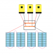
What happens if you discharge 3 packs: 100+100+60Ah (pack A+B+C)
There will be charging of the pack C from pack A+B, true.
But you can set in the C pack BMS to allow charge, and disable discharge until it reaches like 3V (cell UVPR- Under Voltage Protection Release ).
And so you lower the amplitude of this swing (not float on low V but charge). Pack C will not slip under 2,5V. The wear will be much slower (but faster than for pack A and B).
Also every cell in pack C is monitored. Eventually if there is a cell that has extra weak you will notice. BMS shuts down the pack.


And now comes the really interesting part: Charging
As you can imagine, charging occurs almost parallel, based on Ah.
After charging 60Ah cell C is full, 3,65V, little A flowing into it. But still charging.
So you float an already full cell on max charging V for a long time (+40Ah is needed for cell A-B).
That alone is a very very bad thing to do to a cell.
But A-B cells in the last 5%. Vdiff minimal C does not charge them.
And now cell C V rises. Overcharge. There is no BMS to detect that, to stop the charge. BMS knows the average V of the 3 cell (cell C charging A+B).
And that is why you never (fast) charge your EV to 100%. Best not to charge over 90% (we hope SoC diff is below 10% ... and we know they did a proper top balance)


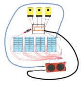
What happens if you charge 3 packs:
BMS simply stops charge on the 60Ah pack after full.
You can twist it even more if you set 3,45-3,55V/cell as full. (cell OVPR- Over Voltage Protection Release)
You really do not need absorption, and you really want to avoid floating at max V.
 
Back
Top