diy solar

diy solar

Is My Multimeter a Dud for Amps?

AgroVenturesPeru

New Member
Joined
Sep 19, 2020
Messages
411
I bought a Prasek PR-54 recently, and watched a video tutorial. The volts seem spot on, which you measure with the diodes. I tested a 9V battery, the wall outlet, and my solar MC4 strings. The first two measurements were spot on. The last one, measuring VOC on a partly cloudy day, seemed also within reason.

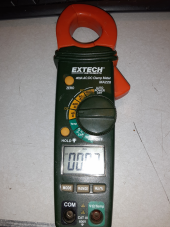
Amps are another story. You have to use the jaws to measure amps. It can supposedly measure ranges of 40A or 400A, but can only measure one wire at a time, so, if you set the unit to AC amps, and measure a cable that holds both Line and Neutral wire, the thing won't even give a reading.

I set it to DC 40A and attached it around the 8 wires heading into my solar string box:

4 Groups, each with a negative and positive.
My array: 4s4p

The first three groups all measured somewhere in the ballpark of 2-3 amps on both their positive and negative cable. Those panels have a Vmp of 41.7V and an Imp of 9.6A.

The fourth group has another brand of panel with mostly the same specs: 41.6Vmp and 9.86Imp.
The positive wire measured about 3 Amps, but the negative wire measured about 6 Amps.

This was pretty consistent, as I measured everything three times over the course of about ten minutes, and the outside light wasn't fluctuating very much during that time frame.
One thing I noticed, was that even when holding the multimeter far away from any wires, it still gave off a reading of around 1 amp. I can understand the thing being inaccurate, but to consistently show a reading of around 3amps on a positive wire, and consistently show a reading of twice that for the same group's negative wire...
 
You only clamp around the red B+ or Ground never both (if I'm reading your post correctly), also should be a calibrate button you push to zero out meter before clamping around wire, my button is marked "Zero" Joe.
1621821217311.png
 
You only clamp around the red B+ or Ground never both (if I'm reading your post correctly), also should be a calibrate button you push to zero out meter before clamping around wire, my button is marked "Zero" Joe.
View attachment 50180
What do you mean "B+" ???

Clamping a ground wire?

Let's simplify things for a second and just talk about the DC wires from the PV array. Are you saying that I should only measure the current from the positive wires?

I'll have to take another look at my manual. I didn't notice any zero button.

When I was reviewing my panel spec sheets just now, the NOCT ratings were actually kind of revealing. The panels are extremely similar under STC conditions, but under NOCT they diverged quite significantly. There is a difference of VOC 2.4V at NOCT vs. VOC 0.1V at STC. Amazing!

Also, the amps start to diverge a little bit too.
Difference of Imp at NOCT: 0.45A
Difference of Imp at STC: 0.26A

I guess that helps explain the variations I saw. I wonder if these would continue to diverge even further if environmental conditions are worse than NOCT? This suggests that the difference would be large on a very cloudy or rainy day.

If anyone's interested these are the spec sheets. I have the 400W version of the Jinko, and the 410W version of the Amerisolar.
 

Attachments

  • JinkoPanelsIhave.pdf
    534.7 KB · Views: 2
  • Amerisolar410PERC.pdf
    2.4 MB · Views: 1
Yes, just clamp a single wire. or all positive or just the hots. If you clamp positive and negative the net amps will be zero. 10 amps positive, 10 amps negative = zero net amps.
 
Clamp meters only work when measuring current in one direction. In a DC line that means measuring either the positive or negative cables, never both at the same time. With AC that means measuring line 1 or line 2 or neutral, not any combination.

Further, the meter will be less accurate for DC current, and the zero function MUST be used. With AC current you measure the current swing, and since you're measuring both positive and negative swings static magnetic fields nearby will cancel out.

With DC it has to measure the absolute magnetic field generated by the current, and this will be affected by the orientation and location of the meter.

To get a reasonably accurate reading try the following:

1. Turn the meter on, set to DC current clamp mode
2. With the clamp fully closed place it NEXT TO but not around the wire you're going to measure, in the same orientation you'll be reading the meter in.
3. Press "zero" and allow the meter to zero.
4. Open the clamp, place it around the wire, and fully close it. Maintain the position and orientation of the meter as much as possible.

You can also clamp the wire for step 2 and zero with the wire disconnected or the circuit off - or even on, zero, then add or remove a load to find the difference. It's similar to using a kitchen scale - you can measure what's added to a bowl without measuring the bowl by zero-ing with the bowl in place.

If the zero wasn't done properly, then the following situation can occur:

Measuring without any wire: 1A
Measuring with positive wire: 3A
Measuring with negative wire: -1A

What you're measuring is a local magnetic field that appears to be a +1A DC current to the meter. This offsets the readings in all three cases by 1A, and you can infer that the actual circuit current is 2A.

DC clamp meters are neat, and I'm so glad they've come down so much in price over the last two decades, but due to the way they work you should be careful acting on their results without understanding their limitations and proper measurement technique.
 
@stienman - clamp meters work in either direction. Depending on which way you put a dc clamp meter, the only difference is that you may not be shown a negative or positive value. So for all practical purposes where one is only concerned with the amount, and not the direction of flow, don't sweat it.
 
Common problem - blowing your multimeters fuse by not moving your leads.

Happened to me a lot. All excited to test a solar panel out of the package not connected to the rest of the system.

Steps on how you blow the fuse: (or what not to do)

1) Set up panel in the backyard isolated just to test voltage and it's short-circuit current. Wires dangling for test.
2) Hooked up multimeter to test voltage. Fine, around 18-20v ocv.
3) Swing multimeter switch to measure AMPS.

4) POOF! There goes an expensive fuse in the Fluke.

Lesson learned - You can't just rotate the multimeter switch. You gotta' move the test-lead jacks on the multimeter to measure current first!

So THAT's why I have voltage but no current from these panels! Time to write up a scathing-review on Amazon in ALL CAPS! :)
 
Back
Top