diy solar

diy solar

Is PWM better over long cable runs to battery?

westoz

New Member
Joined
Apr 2, 2022
Messages
4
Hi all,

I recently switched from a 12v PWM (Curtech CT15A) controller to MPPT (Victron smartsolar 75/15) thinking it would be superior technology and slightly more efficient. However, my setup is such that there is about 6 or 7m of I think 6B&S cable between the reg and the battery (not ideal I know), fed from a 180w panel permanently mounted on the vehicle. What I have noticed is that the PWM seemed to be able to sense battery voltage better over the long cable run than the MPPT. I was hoping someone knowledgeable could confirm or explain what I'm seeing. The voltage readout on the LCD panel on the PWM reg pretty much exactly matched the voltage I was seeing at the battery - lets say for arguments sake this was 14.4v. But the actual voltage being put out by the reg was often a lot higher -close to 15v a lot of the time. So it was as if the PWM reg could read the actual battery voltage and compensate for voltage drop across the cable, and it seemed like the bulk/absorption/float functionality worked properly because of this.

The Victron MPPT I installed recently has a bluetooth app that I can read voltage and current with, and it does not seem to deal with voltage drop at all. For example, I set the absorption voltage at 14.5 and float at 13.5. The Victron app shows the reg in putting out 13.5 volts and whatever amps, but the volts at the battery are only 13.1. I thought about dialling up the absorption and float charge values by 0.5 volts, but I think the voltage drop varies with current and it simply won't work. When I cover the panel with a towel and amps drops to zero the battery voltage and app voltage pretty much match, which confirms its a voltage drop across the cable as current increases I think? So when the system goes into float and current tapers off to zero when the battery is full that extra 0.5 volts I dial in will actually be put into the battery and it will 'float' at 14v.

I'm thinking of just putting the PWM back in but I was hoping someone could explain what's going on here first. I was wondering if maybe the PWM reg reads voltage in between 'pulses', and because there's no current between pulses it gets an accurate reading? I dunno - that sort of thing is beyond my technical understanding.
 
I would say your MPPT controller is superior to your PWM controller in every way except price. I would not switch it out.

My Midnight controllers have a voltage correction setting, which allows you to accurately compensate for voltage drop. If your Victron has the same function, it might not be set properly. I'd go through your manual carefully, and see if it has that function? If it does not, I think and easy fix is simply offset the charging parameters such that your "delivered voltage" matches what you expect it to be, ie; if you set the float value to 13.5 but see 13.1, then set the float to 13.9 so you see 13.5.
 
Maybe your cable isn't large enough and is causing the voltage drop. The MPPT solar charge controller may be putting out more amps than the PWM controller?

Normally, the long run of cable is between the PV panel and the solar charge controller. The cable run between the solar charge controller and battery is as short as possible. Your situation is backwards.

Check all the connections. Did you use a ferrule on the cable going into the Victron? Are the connections clean and tight?
 
Last edited:
Victron state that the controller should be mounted near the battery and to use the correct cable.

Having a long cable run from controller to battery is a mistake often made, even by professional installers. With any equipment reading the instalation instructions and following them is always useful.

The PWM controller that you used previously just had poor performance, less current, and poor voltage control.

Move the controller to a position near to the batteries, within 2 meters and use the cable size recommended for the 15 amps of current. Do not setup higher voltages, this will over charge an possibly damage the battery .

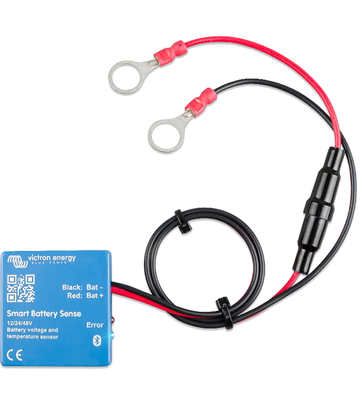
If you fit a Victron Smart Battery Sence unit this will accurately send via Bluetooth voltage and temperature to the controller.


However mounting the controller near the battery with correct cable should be enough for correct performance.

Mike
 
Last edited:
Mount the MPPT close to the battery and see how that goes. If the panels can be switched to series.... do that too.
 
100% understand that the reg should be close to the battery but this is on a 4wd with the battery under the bonnet and this is easier said than done. Under bonnet temps, water crossings etc all mean the reg really has to be inside the car. This introduces a minimum 3m cable run before you even start. Then you have to find somewhere sensible for it to live, and you can't have 0B&S battery cable snaking it's way through the cabin to combat the voltage drop.

Anyway, it looks like with these limitations the Bluetooth battery sensor is the ideal solution. Many thanks everyone for the suggestions - the chocolates go to mikefitz ?
 
Last edited:
OK a controller with voltage sensing would work. Not sure if the Victron has this feature.
 
Hi all,

I recently switched from a 12v PWM (Curtech CT15A) controller to MPPT (Victron smartsolar 75/15) thinking it would be superior technology and slightly more efficient. However, my setup is such that there is about 6 or 7m of I think 6B&S cable between the reg and the battery (not ideal I know), fed from a 180w panel permanently mounted on the vehicle. What I have noticed is that the PWM seemed to be able to sense battery voltage better over the long cable run than the MPPT. I was hoping someone knowledgeable could confirm or explain what I'm seeing. The voltage readout on the LCD panel on the PWM reg pretty much exactly matched the voltage I was seeing at the battery - lets say for arguments sake this was 14.4v. But the actual voltage being put out by the reg was often a lot higher -close to 15v a lot of the time. So it was as if the PWM reg could read the actual battery voltage and compensate for voltage drop across the cable, and it seemed like the bulk/absorption/float functionality worked properly because of this.

The Victron MPPT I installed recently has a bluetooth app that I can read voltage and current with, and it does not seem to deal with voltage drop at all. For example, I set the absorption voltage at 14.5 and float at 13.5. The Victron app shows the reg in putting out 13.5 volts and whatever amps, but the volts at the battery are only 13.1. I thought about dialling up the absorption and float charge values by 0.5 volts, but I think the voltage drop varies with current and it simply won't work. When I cover the panel with a towel and amps drops to zero the battery voltage and app voltage pretty much match, which confirms its a voltage drop across the cable as current increases I think? So when the system goes into float and current tapers off to zero when the battery is full that extra 0.5 volts I dial in will actually be put into the battery and it will 'float' at 14v.

I'm thinking of just putting the PWM back in but I was hoping someone could explain what's going on here first. I was wondering if maybe the PWM reg reads voltage in between 'pulses', and because there's no current between pulses it gets an accurate reading? I dunno - that sort of thing is beyond my technical understanding.
The MPPT should give noticably superior performance. Swapping it back to PWM is unlikely to be helpful.
Your issue appears to be Voltage drop on the cables from SCC to battery. They should be as short as possible so that the SCC can read the battery Voltage with minimal loss. If you must have long cables in the system put them between the Solar source and the SCC input then they will not affect the SCC's ability to correctly manage the battery charging.
Spending a bit more on fatter cables and minimising the distance from SCC to Battery will optimise the performance.
 
@westoz : This situation is similar to those using small camping kits where the charge controller is mounted to the back of the panel, and a long run of cable back to the battery.

NOT good as you've been warned, so just know that you have a compromized setup that performs poorly from voltage drop.

The temptation some make is to compensate for this by purposely setting their CV voltages very high, which will bite you (your battery) later as you've contemplated above.

How? After the battery has finally charged up fully with your overcompensated CV setting, it WILL be driven to that overcompensated high voltage at the very end! Because when *fully charged* there is so little current flowing that voltage drop is much less of a problem, and now the battery sits there at your compensated high voltage cv setting. Snap, crackle, pop and goodbye battery.

So yes, just like those portable panels with the controller at the panel, the only reason it isn't blowing out peoples batteries is that by the poor engineering for convenience, the battery will always be UNDER charged.

But smarties might think "hey, I'll just crank up the CV voltage setting! Brilliant!" That is until they actually DO fully charge the battery and all heck breaks loose with the voltage-drop compensated high voltage.

But don't trust me (I have tested it). Use your own sacrificial battery for testing to prove it.
 
Last edited:
Spot on Substrate - that's exactly why I didn't just crank the target volts up. However, an update on this one - the battery sense struggles with under bonnet temps and did not prove to be a reliable solution. So I have replaced the cable run with very thick battery cable - slightly thicker even than the starter cables on the cranking battery (which in a landcruiser are pretty substantial). I think it was 0 B&S from memory. Both positive and negative leads all the way to the back.

But voltage drop from the solar reg to battery is still 0.3v at about 9 amps. Just enough to be annoying. So it is set to bulk at 14.4 and float at 13.5, but bulks at 14.1 and floats at 13.2.

Any other bright ideas? I'm pretty tempted to maybe split the difference with target voltages - say set bulk at 14.6 and leave float at 13.5?
 
Second update - so after mucking around with voltage drop calculators I realised the remaining 0.3v was probably coming from what I thought was a short run of 6mm (4.58mm2) cable out of the reg to the thicker leads that turned out to be nearly 2m. I did it so long ago I forgot where the cable run actually went. I re-positioned the reg to bring that down to about 60cm and that brought the volt drop back to about 0.07v. I was pretty happy with that but the re-positioned reg also then allowed me to move the battery sense so it's away from under bonnet heat sources (far side of the battery now) and that cleaned up the remaining volt drop nicely with the added bonus of accurate temperature compensation.

Happy days.

The mystery still remains though how the Curtech PWM reg managed to maintain a nice steady 14.4 at the battery in bulk mode, and display 14.4 on the reg, when in actual fact it was pumping out over 15 volts. It really did appear to be compensating for voltage drop but I don't understand how.
 
A lot of wrong beliefs here...

If you previously had PWM there are huge chances that your panel voltage was 18VMPP for a 12V battery, (or 36V MPP to a 24V battery).
That is an ideal match for PWM operation, but a really bad match for MPPT operation !
MPPT operation needs enough voltage headroom above the battery equalization voltage. Just having 3.5V label MPP voltage delta is not enough for an adequate MPPT performance.

If you had 2 piece 18V MPP panels in // to feed your PWM controller, wire them in series with a MPPT controller.

Then you will enjoy all the advantages of a MPPT operation.
 
Last edited:
Back
Top