Good basic start. Devil is in the details.
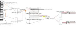
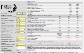
The way you have the panels sketched, it looks like they're in parallel, but you do indicate 2S3P. You will need a fuse or breaker on EACH string, i.e., each 2S gets a fuse/breaker before you parallel them. Given your 240 ft run, you should assess the possibility of using 3S2P as I believe the Midnite 150 has over-voltage protection. The 3S2P might allow you to use a much thinner wire (2awg might be overkill even with 2S). Note that you are not required to fuse/breaker strings with less than 3 parallel strings.
Use:
https://www.calculator.net/voltage-drop-calculator.html (Estimated Resistance tab)
To evaluate wiring scenarios. Start with the appropriately rated wire gauge and then check for voltage drop based on series Vmp and Imp. 3% is generally a good target, but for extreme situations (240' run), one might consider up to 10%. Those percentages will manifest as % power loss.
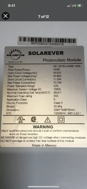
91.7A from panels is not likely. I'm guessing your panel Vmp is around 38V, so 240W/38V = 6.31A?
Maybe you meant 19.7A (3X 6.57A)?
Quick check of voltage drop using the calculator above:
3X Vmp = (240/6.57=36.5) *3 = 109.5V. Again, confirm the Classic has over-voltage protection. I'm almost certain it does.
2X Imp = 6.57 * 2 = 13.14A
8awg wire has a 3.62% voltage drop over 240 ft, 109.5Vmp and 13.14A.
The battery portion is very confusing. The way you have it sketched is as though you have 3X 24V batteries in series.
You appear to be using only one BMS to manage three batteries. That's not typical unless you're using something like a Batrium.
Better to have a BMS for each battery. That allows individual cell monitoring, and it provides redundancy.
Better to have the batteries wired in parallel.
From Victron's Wiring Unlimited in the Resources section (you should read this entire book):
Best to connect 3 as either Diagonally or Busbars
Battery disconnect on each battery. Each battery fused to busbar if you go that route.
Each inverter would get its own connection to a busbar with a fuse/breaker in the (+).
Size wires for current. Size fuses 1.25X current.


 any advise or assistance would be greatly appreciated.