diy solar

diy solar

Is using a Switch mode Power Supply as a Charger A bad idea?

lotsofsparks

New Member
Joined
Jan 9, 2023
Messages
29
Location
Queensland Australia
Hi I'm building an S4 battery the moment my cells arrive and later on this year an S16. Most of the time I will not be using solar panels to charge these batteries because the S4 280Ah Eve battery is for UPS system and Camping sometimes while the S16 Eve 32Ah will be in an escooter. how much ripple can BMS's tolerate from a power supply or would the battery itself buffer enough of it out like a Capacitor even if the cells are small 32AH sized ones but with new like internal resistances?
Could I limit charge Current by Adjusting the supply voltage with an Amp Meter as well?
I was thinking of doing what this guy has done in the video. With the S4 bms connected as well as it being protected with a 30A inline fuse or lower and a 140A (13V or higher) rated DC breaker.
Can small 32Ah EVE cells be stacked on there side 2 or 3 high and withstand the escooter's vibration and bumps?
Charger
I'm using the JBD BMS because it looks awesome It looks like the same bluetooth graphical interface the Overkill BMS.
BMS
Thanks in Advance.
Not a good idea. The SMPS is fine BUT you will need a cc/cv regulator between the battery and the SMPS unless you want to sit and watch your amp meter all day while the battery is charging and twiddling the voltage pot on the SMPS. Buy a proper charger and don't trash your battery ?
 
So In a solar system setting is that one of the solar charge controllers jobs? if i was to use a cheap solar charge controller with a switch mode power supply would that take care of current and voltage regulation for me?
 
So In a solar system setting is that one of the solar charge controllers jobs? if i was to use a cheap solar charge controller with a switch mode power supply would that take care of current and voltage regulation for me?
Theoretically yes it would BUT.........................
1. The input voltage to the SCC (solar charge controller) would need to be 3 to 5 volts HIGHER than the battery voltage depending on MPPT OR PWM, check the specs on the SCC for that.
2. If your using a 12V SMPS then probably the highest voltage you will get out is around 14.5 volts, you need to check on that?
3. So if your 12V battery bank is LIFEPO4 and your maximum charge voltage is 4x3.65=14.6V then the SMPS would need to output around 14.6 +3=17.6V for it to charge your battery bank correctly.
4. your BMS will add a second level of protection for over volts, current etc etc.

Battery's are expensive so my recommendation is to purchase an off the shelf charger BUT saying that i have built my own 30A cell charger (0 to 5V) that consists of a 12V 40A SMPS with a high current buck cc/cv converter on the output (adjustable CC/CV). I use this to top balance cells.
 
323083960_501506488761612_2819372888900632464_n.jpg
 
She aint pretty BUT it does the job.......................maybe i should mount it in an enclosure ;-0
 
I have done and still actively do the ‘SMPS fed through PWM SCC as a battery charger’ thing, multiple ways multiple iterations. I dont feel i have a perfect understanding of it, but yes it does work.

I have found that the only reliable way to have a high enough voltage is just to go to the next available step up on the power supply. So if you are charging a ‘12v’ battery you should just buy a 24v psu etc. 15 is borderline too low, 18 not nearly as available.. 24 is it. Better to have too much than not enough as long as you stay below the charge controller’s PV voltage limit. Just understand that the watt rating of the psu is at its rated voltage. If you sink that voltage way down by connecting it to your battery, the watts of charging it can do go way down as well.

I have suspicions about having the SMPS output being PWM’d affecting their lifespan and i have devised workarounds but i cant say with certainty ‘pwming on the smps output will kill it in a short time period.’ I just think its a factor and try to mitigate it.
 
PWM is not ideal as you are effectively pulse charging it, I've never used PWM for charging but just hazarding a guess. MPPT would be the way to go as it uses a buck regulator to mach the battery V. Also I'm agreed on using a 24v SMPS as the power source.
 
I agree, but since MPPTs tend to cost near what a ‘real’ battery charger does, i dont consider them a go to for this athough in many cases people would already have one. I tend to think the switching frequency of a pwm scc is high enough that the battery itself doesnt actually care, but the psu might. I can actually hear a slight audible difference in some psus when the SCC is pwming them (approaching a current or voltage setpoint) vs just ‘constant on connection’ when it is far from its targets and just leaves the input and output connected full time.
 
It would be interesting to scope the output of the PSU while charging. All the SMPS units i have are short circuit protected so hopefully nothing unexpected happens.........you still have 2 levels of protection after the SMPS, the SCC and the BMS so at least your batteries should be more than protected.
 
Yeah, i think the PSUs are the only things remotely in danger here. I suspect but havent verified that voltage briefly spikes when the PSU’s output is ‘opened’ by the PWM’ing, but im not sure to what extent and whether it’s hazardous to conponents in the psu output section.

I intend to but havent done yet, to hook my psu outputs through several diodes in series to my lead acid bank so that if voltage spikes far above the setpoint it will ‘dump’ into the lead acid bank and i THINK that would ‘clamp’ it from rising any further beyond that point. But this is feasible in my case because my psu>scc>lifepo4 thing is a ‘12v’ system in an rv that also has lead acid 12v so the convenience factor of that approach is high for me, but maybe not practical for someone else’s case.
Theoretically the lithium load is a MASSIVE capacitor that will more than sink any spikes from the SMPS/SCC PWM coupled with the fact that the SMPS has short circuit protection. I'm guessing even the SMPS will be ok.........but don't take my word on that ?
 
Last edited:
Theoretically yes it would BUT.........................
1. The input voltage to the SCC (solar charge controller) would need to be 3 to 5 volts HIGHER than the battery voltage depending on MPPT OR PWM, check the specs on the SCC for that.
2. If your using a 12V SMPS then probably the highest voltage you will get out is around 14.5 volts, you need to check on that?
3. So if your 12V battery bank is LIFEPO4 and your maximum charge voltage is 4x3.65=14.6V then the SMPS would need to output around 14.6 +3=17.6V for it to charge your battery bank correctly.
4. your BMS will add a second level of protection for over volts, current etc etc.

Battery's are expensive so my recommendation is to purchase an off the shelf charger BUT saying that i have built my own 30A cell charger (0 to 5V) that consists of a 12V 40A SMPS with a high current buck cc/cv converter on the output (adjustable CC/CV). I use this to top balance cells.
the buck converter would give you the axtra volts need. Where did you get that buck from?
 
the buck converter would give you the axtra volts need. Where did you get that buck from?
Yes it will if you start modifying the feed back circuitry and potentially upsetting other parts of the SMPS........definitely NOT recommended........fizz, poff, bang with smoke springs to mind ?
 
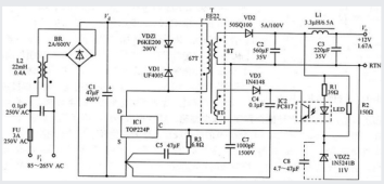
SMPS power supply is not putting out train of DC pulse, it puts out DC with ripple (per spec), you do see bunch of filter caps at the output of the SMPS, correct?
SMPS sch_1.png
 
Yes we know that. The SMPS is feeding it's output into a PWM SCC, because the. SCC is pulsing (PWM) into the battery then the question was how does this affect the output of the SMPS? There will be some effect like increased ripple? On the SMPS. If he were to use a MPPT SCC then there would probably be minimal effect on the SMPS because the MPPT uses a buck regulator to match the battery voltage.
 
SCC is pulsing (PWM) into the battery then the question was how does this affect the output of the SMPS?
Yes, that's the part i am unsure about. And apparently too lazy to scope. I don't have a good electrical understanding of how the output stage works, but i do know something more basic, which is that if i can hear the psu making a different noise when the SCC is PWM'ing it, and sound comes from movement, something in the psu box is physically moving by whatever tiny amount to generate those sound waves, and i suspect nothing in there is designed to move very much! So this is why i feel confident that there is SOME longevity impact to the PSU, of PWM'ing its output, even if i can't speak to the actual electrical effects happening in the circuit.
 
Yes, that's the part i am unsure about. And apparently too lazy to scope. I don't have a good electrical understanding of how the output stage works, but i do know something more basic, which is that if i can hear the psu making a different noise when the SCC is PWM'ing it, and sound comes from movement, something in the psu box is physically moving by whatever tiny amount to generate those sound waves, and i suspect nothing in there is designed to move very much! So this is why i feel confident that there is SOME longevity impact to the PSU, of PWM'ing its output, even if i can't speak to the actual electrical effects happening in the circuit.
The SMPS potentially will make a different noise under load and the noise level depends on the quality of the build. I have on a couple of occasions taken the real noisy ones apart then use an insulated tool to "press" on any inductor/transformer in there. If the noise reduces then get your favorite glue gun into action and fill those windings with glue :) The noise is usually due to mechanically loose windings/core's.
 
Last edited:
The noise is usually due to mechanically loose windings/core's.
That's very interesting. The noises really bother me ?

I connected a 400w 18v switching power supply to a 30a pwm SCC and it worked perfectly for 5 mins and then died.
 
Last edited:
Back
Top